
These are my complete notes for Block Ciphers (Intro & DES) in Symmetric Cryptography.
I color-coded my notes according to their meaning - for a complete reference for each type of note, see here (also available in the sidebar). All of the knowledge present in these notes has been filtered through my personal explanations for them, the result of my attempts to understand and study them from my classes and online courses. In the unlikely event there are any egregious errors, contact me at jdlacabe@berkeley.edu.
Summary of Block Ciphers: Intro & DES (Symmetric Cryptography)
Table Of Contents
IV. Block Ciphers: Intro & DES.
IV.I Historical Background.
#
C. Rule .
Block Ciphers:
A cipher that encrypts a block of 'b' plaintext bits all at the same time, where b is greater than one (since one bit at a time would be a stream cipher). These ciphers are both deterministic and hyper-unpredictable: the encryption of any plaintext bit in a block depends on the value of every other plaintext bit in the block, like the positions of celestial bodies in a galaxy. A one bit difference between two blocks of plaintext will produce two completely different ciphertexts.
Most block ciphers have a block length of 128 bits (16 bytes), such as the AES (see Rule [[[[[), or 64 bits (8 bytes), such as DES and 3DES (see Rule 48 & Rule 56, respectively). For each input, a block cipher will produce an equivalent amount of output data: in the case of DES, this will be another 64 bits.
Block Ciphers are more commonly used than Stream Ciphers in modern computer encryption schemes, due to the stream cipher mass extinction event caused by relentless attacks by cryptanalysts in the '90s, and the mass adoption of block ciphers that followed.
# Product Cipher: A generic term used to describe any cipher that utilizes the methods of permutation (see definition) and repeated encryption (in "rounds") to create the element of "diffusion" necessary for any block cipher (see Rule 45).
#
C. Rule .
Confusion & Diffusion:
During the postwar Cryptographic research boom, stemming from the rush of funding for military science, it was postulated in a classified paper that there were two atomic operations that all good block ciphers should perform:
During the postwar Cryptographic research boom, stemming from the rush of funding for military science, it was postulated in a classified paper that there were two atomic operations that all good block ciphers should perform:
- Confusion:
The relationship between the plaintext and ciphertext must be obscured. Any cipher that scrambles its characters thoroughly enough that the plaintext and ciphertext bare no resemblance to one another, passes this requirement. An example of this is the substitution table, which maps one input bit to a particular output bit the bears no relation to it (see definition). - Diffusion:
The influence of each plaintext bit is spread over many ciphertext bits. In systems making good use of diffusion, changing one bit of plaintext results in an average change of half of the total output bits, known as the Avalanche effect which works akin to chaos theory. Example: Permutations of an encryption method to make a cryptosystem more secure (see Rule 49).
This element is impossible under stream ciphers, since each bit is processed and encrypted individually.
IV.II Feistel Networks.
#
C. Rule .
Feistel Ciphers:
Mathematical Definition:
i ∈ {1, ..., 16}
Li = Ri-1
Ri = (Li-1 + f(Ri-1, ki)) mod 2
i = The particular round that the left and right tranches of the data were created in. The first round produces the tranches L1 & R1, for example.
Li = The left tranche as it is in round i. It will inherit the unencrypted form of the previous right tranche as its starting value in the round.
Li-1 = The left tranche of the round prior to the current one, used by the f function (see below). If i is 1, then it will be L0, the left tranche of the initial input (32 bits of plaintext).
Ri = The right tranche as it is in round i. It will inherit the XOR-ing of the left tranche of the previous round with the encrypted right tranche of the previous round as its starting position.
Ri-1 = The right tranche of the round prior to the current one, used by the f function (see below). If i is 1, then it will be R0, the right tranche of the initial input (32 bits of plaintext).
f = The mysterious encryption function, the central part of the entire Feistel scheme. Uses the right tranche and the subkey of a particular round to make an encryption. Explained in Rule 50.
ki = The specific subkey used in the round. Each subkey is derived from the main key, explained (for DES) in Rule 51.
mod 2 = The modulus/remainder operator with respect to 2. Numbers can only be 0 or 1 in this reality - see Rule 24 for a full treatise.
Explanation:
A Feistel Cipher/Feistel Network/Feistel Structure is a round-based algorithm used to encrypt data. The original, standard, unadorned version of the Feistel Network is depicted below, while the DES-enhanced version can be seen in Rule 48.
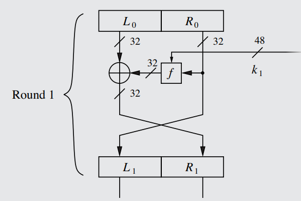 A diagram of an individual round of the Feistel Network, totally unadorned of any additional characteristics specific to the DES system - see Rule 48 for that. The given values and lengths, such as the 48-bit subkey, are all specific to the DES varient.
Widely used among block ciphers (though not in the AES, see Rule [[[), several ciphers like DES developed their own, more optimized versions of the network. The bulk of all modern ciphers currently in use were built using Feistel ciphers and their varients. A particular advantage of the Feistel Network is that decryption and encryption are almost the same operation, with decryption simply being encryption performed in reverse (done using a reversed key schedule to generate the subkeys backwards; see Rule 53).
In terms of importance/usage in the cipher structure, Feistel Networks are the block cipher equivalent of the LFSR, although it actually encrypts the data and requires a key, instead of merely producing the key (like the LFSR). It is just at the same level of ubiquity in block ciphers that LFSRs have for stream ciphers.
Devoid of the more specialized characteristics (particularly those relating to DES, described in Subsection IV.III), the process by which a standard Feistel Cipher encrypts data is simple:
Each round takes in the tranches produced by the previous round (or, in the case of round 1, the inputted plaintext tranches) and converts them algorithmically into new tranches. Thus, each encryption round extends from the tranches above the encryption algorithm to the end-result tranches below it: round 1 takes in tranches L0 and R0 and outputs L1 and R1.
Mathematical Definition:
i ∈ {1, ..., 16}
Li = Ri-1
Ri = (Li-1 + f(Ri-1, ki)) mod 2
i = The particular round that the left and right tranches of the data were created in. The first round produces the tranches L1 & R1, for example.
Li = The left tranche as it is in round i. It will inherit the unencrypted form of the previous right tranche as its starting value in the round.
Li-1 = The left tranche of the round prior to the current one, used by the f function (see below). If i is 1, then it will be L0, the left tranche of the initial input (32 bits of plaintext).
Ri = The right tranche as it is in round i. It will inherit the XOR-ing of the left tranche of the previous round with the encrypted right tranche of the previous round as its starting position.
Ri-1 = The right tranche of the round prior to the current one, used by the f function (see below). If i is 1, then it will be R0, the right tranche of the initial input (32 bits of plaintext).
f = The mysterious encryption function, the central part of the entire Feistel scheme. Uses the right tranche and the subkey of a particular round to make an encryption. Explained in Rule 50.
ki = The specific subkey used in the round. Each subkey is derived from the main key, explained (for DES) in Rule 51.
mod 2 = The modulus/remainder operator with respect to 2. Numbers can only be 0 or 1 in this reality - see Rule 24 for a full treatise.
Explanation:
A Feistel Cipher/Feistel Network/Feistel Structure is a round-based algorithm used to encrypt data. The original, standard, unadorned version of the Feistel Network is depicted below, while the DES-enhanced version can be seen in Rule 48.
Widely used among block ciphers (though not in the AES, see Rule [[[), several ciphers like DES developed their own, more optimized versions of the network. The bulk of all modern ciphers currently in use were built using Feistel ciphers and their varients. A particular advantage of the Feistel Network is that decryption and encryption are almost the same operation, with decryption simply being encryption performed in reverse (done using a reversed key schedule to generate the subkeys backwards; see Rule 53).
In terms of importance/usage in the cipher structure, Feistel Networks are the block cipher equivalent of the LFSR, although it actually encrypts the data and requires a key, instead of merely producing the key (like the LFSR). It is just at the same level of ubiquity in block ciphers that LFSRs have for stream ciphers.
Devoid of the more specialized characteristics (particularly those relating to DES, described in Subsection IV.III), the process by which a standard Feistel Cipher encrypts data is simple:
- The data path will be split into two parts: a Left and a Right tranche, L0 and R0 respectively. For a 64 bit cipher (like DES), each tranche will have 32 bits.
- The Right tranche will have its bits fed into the f function, which is the actual encryption function of the entire operation.
Additionally, a subkey will also be fed into the f function: In each round of encryption, a new subkey derived from the main key is used, thus keeping the process deterministic and replicable, but complicating the process so much that discovery of the plaintext from knowledge of the ciphertext is made (most likely) impossible.
In the DES cipher, which differs from the more generalized standard Feistel network described here and shown in the graphic, the subkey is created using a key schedule. See Rule 51 for an explanation of how this is carried out.
The length of the subkey does not have to be exactly as long as either tranche - in DES, the subkey is 48 bits long, the purpose of which is explained in Rule 51, step 4. - The output of the encryption of the right tranche will then be XOR'd bit-by-bit with the left tranche (which had gone untouched until now).
- For each round, the output of the previous round is fed in as input to the next round. The trick at this juncture is that the tranches will switch their positions in the new round: the right tranche will become the new left tranche (L1), and the left tranche will become the new right tranche (R1).
IMPORTANT NOTE: The Right tranche is sent to the left tranche of the next round in its unencrypted form, while the right tranche of the next round is sent the encrypted output of steps 2-3. Since the Left tranche of the first round got XOR'd with the encrypted version of the Right tranche, the LEFT tranche is the one being "encrypted" during any particular round, not the right tranche. Although an encrypted version of the Right tranche is used to encrypt the Left tranche, the encrypted version of the right tranche is not used for any other purpose than to change the left tranche, since it is the unaltered version of the right tranche that gets sent to the next round.
Each round takes in the tranches produced by the previous round (or, in the case of round 1, the inputted plaintext tranches) and converts them algorithmically into new tranches. Thus, each encryption round extends from the tranches above the encryption algorithm to the end-result tranches below it: round 1 takes in tranches L0 and R0 and outputs L1 and R1.
IV.III Data Encryption Standard.
#
C. Rule .
History of the Data Encryption Standard (DES):
Proposed in 1974 by IBM (in coordination with the NSA), DES was the cryptographic standard for the U.S. government between 1977 and 1998, making it the most studied cipher in the world.
DES was the first "secure" cryptosystem ever made public by a national government under the postulate of Kerckhoffs's principle (see Rule 3).
Today, there are still some varients of DES that see application: notably, 3DES, which was used in Firefox until 2021. While the original DES, as developed in 1974, is unsecure from Brute-Force attacks due to its short key-length (56 bits), 3DES has a very long key, and as such is immune to such attacks. For information on 3DES, see Rule 56.
# Look-up Table/Substitution Table: An algorithm in which every input is paired with a particular value/address, and has that value outputted. Occasionally, when used in the context of a Permutation (see definition), they will be called Permutation Tables.
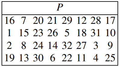
Almost all substitution tables (including permutation tables) are read in terms of position and value. Each value in the table represents a position that the bit at the position of its position-value is moving toward. Seriously. The table illustrated below, for example, is moving the 1st bit to position 16, and the 2nd bit to position 7, and so on for all 32 bits. Of course, the bits at positions 16 and 7 are also moving into positions 1 & 2, respectively. The bits swap.
Examples of tables read like this can be found in Rule 49 and in Rule 50, step 4. An exception to this format of interpreting substitution tables is the DES S-box, which uses its own weird system detailed in Rule 50, step 3. The S-boxes are also a rare exception in which the number of output bits does not match the number of inputted bits - each table produces 4 output bits from 6 input bits.
# Bijection: The mapping of every possible input uniquely to exactly one output, and vice versa. DES (see Rule 48), for example, bijectively maps a 64-bit input block to a 64-bit output block using the principle of diffusion (see Rule 45): a difference in a single input bit will change the entire output block, thus making the blocks themselves bijectively mapped, but not the bits (since the ciphertext bit mapped to by a particular plaintext bit will change if any other plaintext bit in the block is altered).
#
C. Rule .
Data Encryption Standard (DES):
Mathematical Definition:
There is no overarching equation that describes DES as a whole - the algorithm is too complex and has too many interlinking parts to be cohesively represented mathematically. The closest thing to an equation for DES is the proof that the decryption and encryption functions use the same operations, derived and explained in Rule 52.
Explanation:
The Data Encryption Standard is a 56-bit block cipher that encrypts 64 bits at a time, outputting 64 bits of ciphertext in return through bijective mapping (see definition). As a product cipher, DES uses 16 encryption rounds of an optimized form of the Feistel Network (depicted below) to thoroughly obfuscate and diffuse the impact of each bit, following the known elements of best-practice block ciphers (see Rule 45).
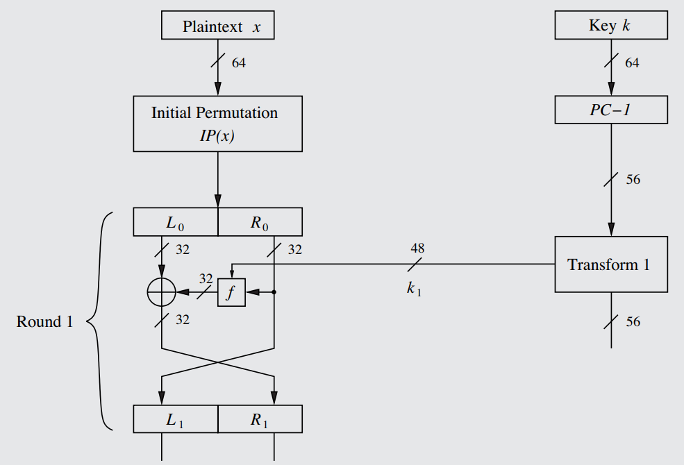 A diagram of an individual round of the DES-specific optimized version of the Feistel Network, complete with a representation of how the subkey is formed from a transform of the main key. On the right hand side is the key schedule, described in Rule 51.
The key-length of DES is 56 bits (and thus has a keyspace of only 2^56 under the relation given in Rule 6) and highly crackable, and so it is not in popular use today - it has been largely replaced by other ciphers with longer keys, such as 3DES (Rule 56) and AES ([[[[[). Still, it remains useful and neccesary to study the design of DES, which is modern Cryptography in its embryonic state. See Rule 55 for information regarding the brute-forcing of DES and its feasibility. The subkeys used in each round of the DES Feistel Network are only 48 bits each - see Rule 51, step 4 for why that is. Additionally, see Rule 51, step 1 for why DES is 56 bits.
Mathematical Definition:
There is no overarching equation that describes DES as a whole - the algorithm is too complex and has too many interlinking parts to be cohesively represented mathematically. The closest thing to an equation for DES is the proof that the decryption and encryption functions use the same operations, derived and explained in Rule 52.
Explanation:
The Data Encryption Standard is a 56-bit block cipher that encrypts 64 bits at a time, outputting 64 bits of ciphertext in return through bijective mapping (see definition). As a product cipher, DES uses 16 encryption rounds of an optimized form of the Feistel Network (depicted below) to thoroughly obfuscate and diffuse the impact of each bit, following the known elements of best-practice block ciphers (see Rule 45).
The key-length of DES is 56 bits (and thus has a keyspace of only 2^56 under the relation given in Rule 6) and highly crackable, and so it is not in popular use today - it has been largely replaced by other ciphers with longer keys, such as 3DES (Rule 56) and AES ([[[[[). Still, it remains useful and neccesary to study the design of DES, which is modern Cryptography in its embryonic state. See Rule 55 for information regarding the brute-forcing of DES and its feasibility. The subkeys used in each round of the DES Feistel Network are only 48 bits each - see Rule 51, step 4 for why that is. Additionally, see Rule 51, step 1 for why DES is 56 bits.
# Bit Permutation/Bitwise Permutation: The process in which bits are scrambled and assigned to different positions in the data than they were before. It's effectively the algorithmic term for a crosswiring. These operations require the use of a substitution table (see definition), which are known as permutation tables in this context. See Rule 49 how this can be carried out in an actual cryptosystem (and why).
Note that the verb form of permutation is not "permutate", but rather "permute".
#
C. Rule .
DES Internals #1 - Initial & Final Bit Permutations:
The first characteristic one may note about the DES Feistel Cipher (as depicted in the graphic of Rule 48) is that the first operation undergone by data being processed by the cipher, even before it is split into tranches, is IP(x), the Initial Permutation function. Undepicted is the very last operation in the encryption process, at the bottom of the cipher (which is 16 rounds deep), where the IP(x)⁻¹, the Final Permutation, would be located.
IP(x) and IP(x)⁻¹ are simple bit permutations, or bitwise permutations, detailed in the definition above. Essentially, IP(x) just scrambles the bits and places them in different parts of the 64-bit sequence. IP(x)⁻¹, being the inverse of IP(x), perfectly undoes the scrambling of IP(x) at the end of the cipher (after all the bits have been fully encrypted), cancelling eachother out.
The purpose of the DES bit permutation functions is simple: while serving no cryptographic purpose (since the attacker can simply take the permutation into account, and because it is undone anyway), when DES was designed in 1974, the application of the cipher into hardcare necessitated cross-wiring (physical bit permutation) just to allow the data to enter the chip. The specific bit permutations used for the initial and final permutations (both depicted in the illustration below) are done in order to, according to leading experts on the issue, "arrange the plaintext and ciphertext bits in a bytewise manner to make data fetches easier for the 8-bit data buses [widely used in the '70s]."
Below are the specific bit permutation tables hand-selected for the DES cipher. For any value in either box, look for the value in the other box whose position-value is the first value - this will determine what the first value maps to. For example, the value '58' in the IP box maps to '1' in the IP⁻¹ box, since 1 is in the 58th position in IP⁻¹. Likewise, '1' in the IP⁻¹ box maps to 58 in the IP box since 58 is in the 1st position. Note that these values represent the bits at these positions in the 64-bit sequence being mapped to other bits.
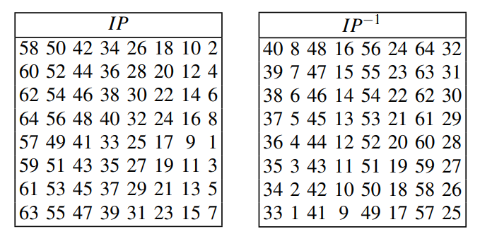 The Initial and Final Permutation Tables in the DES cipher.
Thus, the bit permutations were merely placed in DES for practical, electrical engineering purposes, devoid of cryptographic meaning. DES was initially designed purely for hardware, and the electrical engineering-devised permutation (no gates or special operations) made it very easy to be fabricated in hardware form, but somewhat tedious and more time-consuming in software.
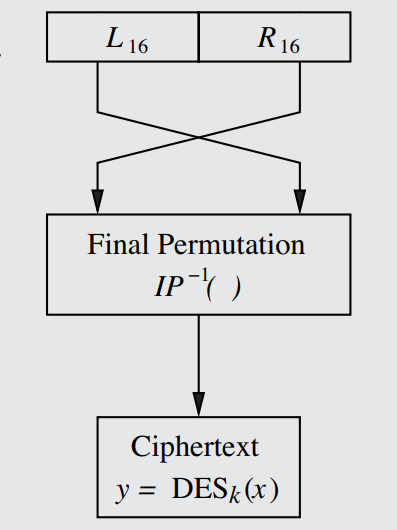 The Final Permutation in the DES cipher.
Note that the tranches of the Feistel Network (see Rule 46) are switched for the final time at IP(x)⁻¹, which is very important to know for the decryption function (see Rule 52).
The first characteristic one may note about the DES Feistel Cipher (as depicted in the graphic of Rule 48) is that the first operation undergone by data being processed by the cipher, even before it is split into tranches, is IP(x), the Initial Permutation function. Undepicted is the very last operation in the encryption process, at the bottom of the cipher (which is 16 rounds deep), where the IP(x)⁻¹, the Final Permutation, would be located.
IP(x) and IP(x)⁻¹ are simple bit permutations, or bitwise permutations, detailed in the definition above. Essentially, IP(x) just scrambles the bits and places them in different parts of the 64-bit sequence. IP(x)⁻¹, being the inverse of IP(x), perfectly undoes the scrambling of IP(x) at the end of the cipher (after all the bits have been fully encrypted), cancelling eachother out.
The purpose of the DES bit permutation functions is simple: while serving no cryptographic purpose (since the attacker can simply take the permutation into account, and because it is undone anyway), when DES was designed in 1974, the application of the cipher into hardcare necessitated cross-wiring (physical bit permutation) just to allow the data to enter the chip. The specific bit permutations used for the initial and final permutations (both depicted in the illustration below) are done in order to, according to leading experts on the issue, "arrange the plaintext and ciphertext bits in a bytewise manner to make data fetches easier for the 8-bit data buses [widely used in the '70s]."
Below are the specific bit permutation tables hand-selected for the DES cipher. For any value in either box, look for the value in the other box whose position-value is the first value - this will determine what the first value maps to. For example, the value '58' in the IP box maps to '1' in the IP⁻¹ box, since 1 is in the 58th position in IP⁻¹. Likewise, '1' in the IP⁻¹ box maps to 58 in the IP box since 58 is in the 1st position. Note that these values represent the bits at these positions in the 64-bit sequence being mapped to other bits.
Thus, the bit permutations were merely placed in DES for practical, electrical engineering purposes, devoid of cryptographic meaning. DES was initially designed purely for hardware, and the electrical engineering-devised permutation (no gates or special operations) made it very easy to be fabricated in hardware form, but somewhat tedious and more time-consuming in software.
Note that the tranches of the Feistel Network (see Rule 46) are switched for the final time at IP(x)⁻¹, which is very important to know for the decryption function (see Rule 52).
#
C. Rule .
DES Internals #2 - The 'f' Function:
The f function, the heart of the Feistel Network (and thus of DES), acts similarly to a PRNG, using the two input parameters Ri-1 (32 bits) and ki (48 bits) to "encrypt" the right tranche (encrypt in quotations because this encrypted version will only be used to XOR the left tranche, while the unencrypted right tranche will move on to the next round, as detailed in Rule 46).
Ri-1 is the tranche created in the previous round (since each round creates its tranches using the tranches of the previous round; see Rule 46), while ki is the subkey for that particular round (see step 2). Below are the complete contents of the f function, with each step labeled (and each individually described at length further below):
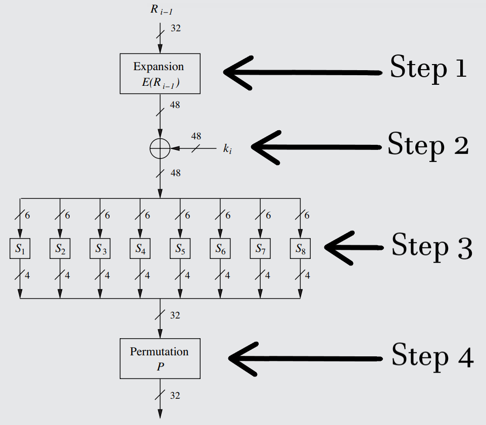 The complete f function of the DES-specific Feistel Network, with each step labeled.
The f function, the heart of the Feistel Network (and thus of DES), acts similarly to a PRNG, using the two input parameters Ri-1 (32 bits) and ki (48 bits) to "encrypt" the right tranche (encrypt in quotations because this encrypted version will only be used to XOR the left tranche, while the unencrypted right tranche will move on to the next round, as detailed in Rule 46).
Ri-1 is the tranche created in the previous round (since each round creates its tranches using the tranches of the previous round; see Rule 46), while ki is the subkey for that particular round (see step 2). Below are the complete contents of the f function, with each step labeled (and each individually described at length further below):
-
The first operation that will be performed will solely involve the first parameter: Ri-1. In order to account for the differences in length between the right tranche and the subkey, the right tranche will be expanded from 32 bits to 48 bits, using the special "Expansion function" or "Expansion box", also referred to as simply the "E-box".
The E-box is a non-bijective variation of the standard bit permutation (see definition), in that some of the inputted bits are connected to two bit positions, creating values for an expanded table. With the initial 32-bit string of the right tranche, 16 bits of data will be connected only once, while the other 16 bits will be connected twice. An example of how this can be done is seen in the illustration below.
Notably, this function will provide diffusion to the cipher, as its effects will increase the significance & influence of each individual bit of the plaintext with every additional round of encryption.
The permutation performed by the Expansion box.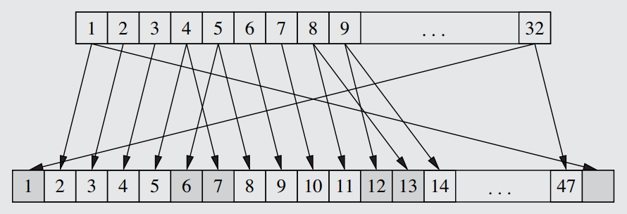
- With the newly 48-bit right tranche, an XOR operation can be performed between the tranche and the subkey (which has its own special means of derivation, explained in Rule 51). This produces a 48-bit string that successfully alters the data using a key.
-
After the XOR, the string must be shrunk back down to 32 bits so that it can be XOR'd later on with the data from the left tranche (outside of the f function). This requires the uses of the S boxes, arguably the most important part of the f function. Complementary to the diffusion of the E-box, the S-box will provide the confusion element of the cipher (as well as more diffusion - see the "Design of DES S-Boxes" blue section).
The pattern the S-box follows is simple, and is shown in the complete f function diagram further above: The newly-created 48-bit string will be split into 8 sub-tranches of 6 bits. Each sub-tranche will be sent to a Substitution Table (see definition), S1 through S8. These tables will work akin to compression functions/compression boxes in the exact opposite manner to the E-box, as they produce less output than input: Each table will output 4 bits from an input of 6, thus resulting in a net total of 32 bits, exactly what is needed.
The Compression Algorithm works as follows: Since each table accepts 6 bits, which are read in their combined, binary form, the table is simply taking the given 6-bit value (0-63) and replacing it with a 4-bit value (0-15). The chosen 4-bit replacement value for each possible 6-bit value is assigned according to a predetermined substitution table. For information as to what exact criteria the S-boxes were designed with in mind, see the relevant "Design of DES S-Boxes" blue section below.
Note that EACH S-box, S1 through S8, has its own, individual, substitution table. While the S1 table is shown below, the rest of the tables can be found on page 3 of this document here.
The specific, exact table used in the first S-Box to replace the 6 bit string with a (max) 4 bit one. Chosen by IBM & the NSA to be differential cryptanalysis-proof (see "Design of DES S-Boxes").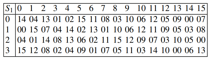
In order to read the table, you must take the 6-bit value and examine it as follows:
For the Column Select, take the middle 4 values (the internal, non-edge values) and find their individual value in binary, separate from the rest of the string. This will give you a value 0-15.
For the Row Select, simply combine the left and right edge values of the 6-bit value in a single binary number, 0-3. This will serve as the row value.
All that needs to be done to find the 4-bit output (represented in decimal in the given table and in all others) is to locate it on the table using the known column and row values. The binary representation of the located value is then concatenated with the results from all the S-boxes, forming a 32-bit string that passes onto the final step. -
All that is left to be done within the f function after the compression from the S-boxes of step 3 is a simple bit permutation, which works in a different fashion to the IP(x) and IP(x)⁻¹ described in the Rule 49.
This permutation has a legitimate cryptographic purpose: the collective output bits of the S-boxes from step 3 are scrambled in such a way that the individual bits are positioned to affect more S-boxes in the following round. If even a single bit is flipped in the input, it will progressively affect more S-boxes each round and will eventually change the entire output. Thus, this permutation hastens the avalanche effect and contributes further diffusion to the cipher.
Each round uses the same permutation table, seen below. Of course, as before in Rule 49, it must be read in terms of both position and value - the 1st bit is moved to position 16, while the 2nd is moved to position 7, and so on.
The permutation table/substitution table used in each round of the f function to move the bits around the sequence.
# Most Significant Bit (MSB): The leftmost bit in a binary number - the largest value representation in the binary place value system. This varies from system to system.
# Least Significant Bit (LSB): The rightmost bit in a binary number (2^0) - the smallest value representation in the binary place value system.
# Design of DES S-Boxes:
The purposeful and exact design of the S-boxes in the DES cipher was done to ensure protection against Differential Cryptanalysis ([[[[[[[[), which researchers at IBM discovered decades before the academics of the late '80s. The design of both the mechanism for ensuring diffusion in the output and of the substitution tables themselves was performed by the NSA and IBM under the following specific criteria, ranging from the obvious to the esoteric:
- Each S-box must have six input bits and four output bits, as to have an end total of 32 bits (to allow for XOR-ing with the left tranche).
- No single output bit should be too close to a linear combination (Linear Algebra - Math Rule [[[[[[) of the input bits.
- If the lowest and the highest bits of the input are "fixed" (i.e., constant) and the four middle bits are varied (i.e., nonconstant and cycling through every possible value), each of the possible 4-bit output values must occur exactly once.
- For any nonzero 6-bit difference between inputs into a substitution table (like 101001 and 010110), no more than 8 of the 32 pairs of inputs exhibiting that 6-bit difference may result in the same output difference. Thus, for all 32 possible pairs of 6-bit differences (pairs that when XOR'd together, produce 111111), a maximum of 8 can have the same number of bits differing between their outputted 4-bit strings. This is a really esoteric requirement that demonstrates the precision of the requirements to maximize diffusion, and how narrow the conditions for success were for defense against differential cryptanalysis.
- A collision (identical S-box outputs, known as a "Zero Difference") of the outputs of the eight S-boxes must only be possible for a maximum of three adjacent S-boxes. Two adjacent colliding S-boxes would thus be fair game.
If it were possible for all 8 boxes to have a zero difference, then the S-box design would have a highly predictable structure. - If two inputs to an S-box differ by exactly one bit, their outputs must differ by atleast two bits.
- If two inputs to an S-box differ in two middle bits, their outputs must differ by atleast two bits.
- If two inputs to an S-box differ in their first two bits, but are identical in their last two bits, the two outputs must be different.
The design of all eight of the substitution tables incorporates both the need for being differential cryptanalysis proof, and all of the diffusion-specific requirements above. This is why the S-boxes are the heart of the f function, and by extension the heart of the Feistel Network, and thus the heart of DES.
#
C. Rule .
DES Internals #3 - Key Schedule:
A Key Schedule is an algorithm used to generate the subkey for every round of a product cipher, working almost like a mini-DES using its own permutations and round system to supply the subkeys. While every cipher has its own variation on how the key schedule will exactly work, the general form is practically always the same. The following Rule will detail how the DES Key Schedule works in particular, which is the simplest, most bare-bones, non-mathematical version of the key schedule you can get. In discussions of other ciphers, deviations from the DES standard with be noted rather than rederiving the wheel, and knowledge of the DES key schedule will be assumed as a basis to build off of. A detailed description of how a Reversed Key Schedule can be used in decrypting DES can be found in Rule 53.
In DES, using a series of fairly simple operations, the key schedule is able to shrink the inputted key from 64-bits to 56-bits, and then from there into sixteen 48-bit subkeys. The reason that DES doesn't just use 64-bit subkeys (adjusting the E-box and S-box's appropriately) is because [REDACTED].
A 64-bit key is inputted into the key schedule and goes through a series of operations before 16 subkeys (k1 through k16) are derived from it to supply each of the 16 encryption rounds, each subkey consisting of 48 bits. Each operation in this process is described in the paragraphs, in the order that the bits travel from entry into the key schedule to the creation of the final subkey. The illustrations below depict the placement of the Key Schedule in relation to the rest of the DES cipher, as well as the internal details of the Key Schedule and their steps.
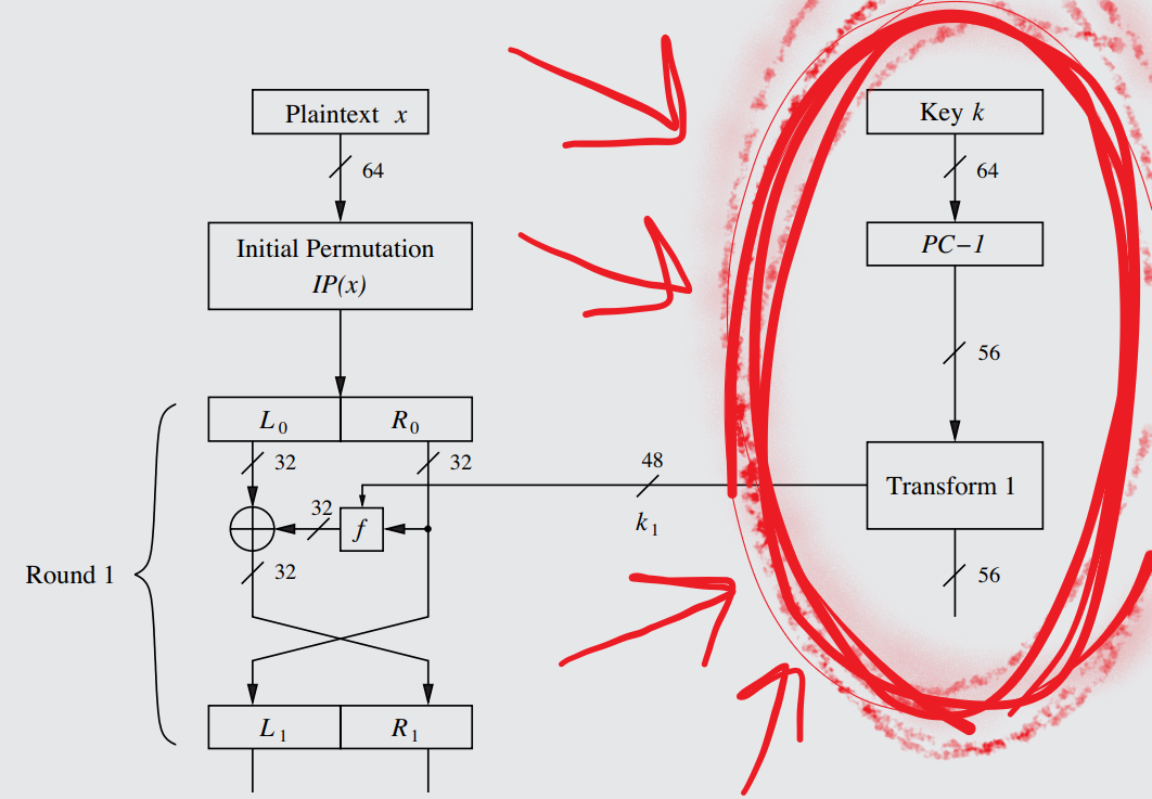 The DES Feistel network, with the Key Schedule circled in red so you don't miss it.
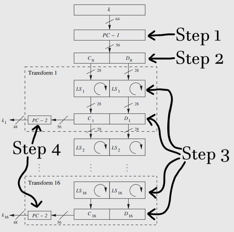 A closeup of the Key Schedule, with the finer details of the Transforms shown. Each step is described in detail in the paragraphs below.
A Key Schedule is an algorithm used to generate the subkey for every round of a product cipher, working almost like a mini-DES using its own permutations and round system to supply the subkeys. While every cipher has its own variation on how the key schedule will exactly work, the general form is practically always the same. The following Rule will detail how the DES Key Schedule works in particular, which is the simplest, most bare-bones, non-mathematical version of the key schedule you can get. In discussions of other ciphers, deviations from the DES standard with be noted rather than rederiving the wheel, and knowledge of the DES key schedule will be assumed as a basis to build off of. A detailed description of how a Reversed Key Schedule can be used in decrypting DES can be found in Rule 53.
In DES, using a series of fairly simple operations, the key schedule is able to shrink the inputted key from 64-bits to 56-bits, and then from there into sixteen 48-bit subkeys. The reason that DES doesn't just use 64-bit subkeys (adjusting the E-box and S-box's appropriately) is because [REDACTED].
A 64-bit key is inputted into the key schedule and goes through a series of operations before 16 subkeys (k1 through k16) are derived from it to supply each of the 16 encryption rounds, each subkey consisting of 48 bits. Each operation in this process is described in the paragraphs, in the order that the bits travel from entry into the key schedule to the creation of the final subkey. The illustrations below depict the placement of the Key Schedule in relation to the rest of the DES cipher, as well as the internal details of the Key Schedule and their steps.
-
The first operation the 64-bit key will pass through in the key schedule is the "PC–1" box, which stands for "Permuted Choice One". It serves to both remove every 8th bit to shorten the key, and to perform a simple permutation on the remaining bits.
Many cryptographic textbooks describe the PC-1 box as removing "parity bits" from the string. But that is cop-out: the usage of parity bits in electrical engineering (see E.E. [[[[[) is completely irrelevant to cryptography. As such, let it be known without the obfuscation of additional E.E. terminology: PC-1 removes every 8th bit from the key. 8, 16, 24... all removed for the simple reason of [REDACTED], which is also the reason why DES doesn't just accept 56-bit keys.
After the culling of those eight poor bits, the other 56 bits undergo a simple permutation (see definition), scrambling the bits using the permutation table found here.
This is why DES is said to have a key-length of 56 - each 48-bit subkey (the final versions of which are created in step 4) is derived from these 56 bits. While it is true that the 56 bits were originally derived from the 64 bits, each of the 56 bits is used in atleast one of the 16 subkeys (as shown in step 3), while the 8 culled bits of the initial 64-bit key are lost forever and thus irrelevant to the cipher as a whole. Thus, the key-length of DES is 56 bits. - The key in its new 56-bit form will then be evenly split into the C0 and D0 tranches, each with a length of 28. This is the final pre-transform step, and just serves to get the data into position before it enters into the most important stage of the schedule (see step 3).
- After this, the key schedule proper can begin, with every step before step 3 essentially being set-up for the great subkey generator: the "Transform". The transform is the part of the key schedule that is repeated for each round of the Feistel Network, generating and supplying a new subkey to the f function of each round (see the illustration of Rule 48). Each transform is, in and of itself, composed of 4 steps in which the subkey is generated before moving onto the next transform to generate the next subkey.
The first step of the transform is what is known as the Left Shift, or Left Rotate (represented as LSi), which literally just cyclically shifts every bit in each tranche leftward by a set number of places. This works a bit like modular arithmetic in reverse, with each bits that moves to the left of the first position being moved to the very end of the sequence. Both tranches will have their bits move the same number of places.
What is most interesting about this rather simplistic process is that the number of places each bit moves leftward differs depending on which round the transform is at. LSi, i being the particular round, is governed by the following rule:
For the rounds 1, 2, 9, & 16, the leftward shift is by one bit.
For all rounds OTHER than 1, 2, 9, & 16, the leftward shift is by two bits.
While rounds 1, 2, 9, & 16 were arbitrarily chosen to be one-bit rotations, the reason for the difference in the number of shifts is so that the total number of rotations will reach 28 by round 16: (4 × 1) + (12 × 2) = 28. Therefore, by the final round, the leftward shifts will have accumulated enough to make the 16th subkey tranches (C16 & D16) identical to the subkey tranches produced before the 1st round (C0 & D0). This is of the utmost utility for when the time comes to decrypt, which, as detailed in Rule 53, entails going through the key schedule in reverse. The reason the leftward shifts are being bothered with at all is also rather simple: it is just a kind of lazy way of creating different subkeys, like the least effort way of doing so. It literally just shifts everything over by a bit or two.
The end result of this shift operation will be two shifted tranches whose index matches their transform - in the key schedule illustration, for example, it can be seen that the tranches C1 & D1 were created in Transform 1 by performing a left rotation on the starting tranches of C0 & D0. Thus, each transform uses a left rotation on the tranches of the previous transform to create its own tranches.
Since the final step of the bit permutation of step 4 uses the same table for each subkey, the leftward shift is really the only thing that differentiates one subkey from another, though the scrambling of the bit permutation (and the culling of another eight bits) renders the end-result subkeys totally unrecognizable from one another. - The final step of the transform before the subkey gets shipped off to the f function to get XOR'd (see Rule 50, step 2) is to perform another bit permutation/culling operation, basically identical to step 1 in every way except this time going from 56 bits to 48 bits (making it the same size as the post E-box right tranche that it is going to be XOR'd with in the f function - see Rule 50, steps 1 & 2). The tranches are combined in order to do this.
This operation, represented as PC-2 on the diagram ("permuted choice 2"), removes eight bits and then scrambles those remaining using the permutation table found here. After this, the subkey (now finally granted the title of "ki" for its round) is sent to its final destination: an XOR gate in the f function.
Note on the diagram how only the unpermuted version of the tranches passes on to the next transform - the 48-bit permuted subkey goes off on its own adventure to the f function, while the more serious 56-bit unpermuted tranches stay to complete the rest of the subkeys for the remaining rounds.
#
C. Rule .
DES Decryption (Feistel Network):
One of the most useful features of the Feistel Nework, particularly taken advantage of by DES, is the simplicity of the decryption function. It stands that for any Feistel-based cipher, the decryption function is just the encryption in reverse. Every attribute except for the general structure of the Feistel Network is done in reverse - the decryption versions of both the Feistel network (described below) and the key schedule (described in Rule 53) look identical to the encryption version, except with different variables and (for the key schedule) some different operations perfomed. While the ciphertext can just be fed in as normally into the Feistel Network (for reasons outlined below), the Key Schedule must be altered to incorporate a Right Rotation rather than a Left Rotation, described in detail below.
Of course, all the other annoying little ornaments of DES need to be accounted for as well, such as the initial and final permutations (IP(x) & IP(x)⁻¹) detailed in Rule 49. IP(x)⁻¹e is the IP(x)d of the decryption function, and vice versa.
It is useful to think of the decryption function as merely being the encryption function flipped on its head. For each decryption round Fid and each encryption round Fie, F1d will reverse F16e, F2d will reverse F15e, and so until F16d reverses F1e and you are left with (after the final permutation) the plaintext.
Tranchewise, because of how the left and right tranches are swapped when they enter the Final Permutation (see Rule 49), and because the final permutation of the encryption function is equal to the initial permutation of the decryption function (which does NOT swap the tranches), the initial left and right tranches of the decryption function are equal to the final right and left tranches of the encryption function: L0d = R16e, while R0d = L16e.
It can hence be mathematically proven that every following Lid is equal to R16-ie, and that every Rid is equal to L16-ie. The following proof is simplified WLOG to the first round decryption, the same process of which can be applied to any round of the decryption:
1. L1d = R15e
2. R1d = L0d ⊕ f(k1d, R0d)
3. R1d = L15e ⊕ f(k16e, R15e) ⊕ f(k1d, R0d)
4. R1d = L15e ⊕ f(k16e, R15e) ⊕ f(k16e, R15e)
5. R1d = L15e
The 1st step originates from the fact that for each round of a Feistel Network, the right tranche moves unaltered to the left tranche of the next round (depicted and described in Rule 46). For the decryption function, this means that L1d is equal to R0d. As noted above, the swap into the final permutation of the encryption function (and the lack of a swap in the first permutation of the decryption function) makes it so that R0d is equal to L16e, which itself, again as a left tranche, is equal to R15e, the right tranche of the previous round.
The 2nd step is more straightforward: the right tranche of the first round of the decryption is equal to the XOR'ing of the subkey for that round with the left tranche of the 0th round (the initial tranches).
Step 3 entails more substitutions: Because L0d, using the final permutation, is equal to R16e, it can be substituted out for the XOR that represents R16e in the encryption equation. This creates two f function XOR gates, and cancelling them will succeed in the end goal of an isolated L15e.
To cancel out the two XOR'd f functions shown in step 3, it must be shown that they are equal to eachother, since a value XOR'd by itself equals 0. Crucial to Step 4 is the fact that same subkey (K16) is used for both the 16th round of the encryption function and the first round of decryption function, which is ensured using a reversed Key Schedule (see Rule 53). Furthermore, as previously established in step 1, R0d is equal to R15e, and performing both substitutions proves that the two f functions are indeed equal to one another.
Step 5: Finally, since L15e XOR'd by 0 is just L15e, the proof is q.e.d. and completed. The process can be repeated for any round i of the decryption function to prove that its tranches are equivalent to the tranches at round 16-i of the encryption function (with the left tranche of one being the right tranche of the other, of course).
#
C. Rule .
Reversed Key Schedule:
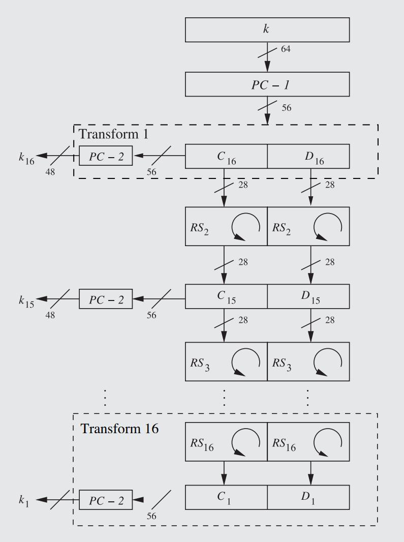 The Reversed DES Key Schedule. Note that each round, each subkey subscript, corresponds to the reversed Feistel network.
The Reversed Key Schedule (depicted above) is the regular Key Schedule (see Rule 51), except generated in reverse order for the decryption function of DES (described in Rule 52). The Reversed Key Schedule has every subkey generated from the original 64-bit key, and at first runs exactly the same as the original key schedule (see Rule 51) - the key is shortened to 56-bits in the PC-1 box, and procedes to be divided into two tranches.
However, the first major difference appears immediately afterward: Instead of having the rotation performed before the subkey is sent off to the Feistel f function, it is now done afterwards. This is done for the purposes of having the subkeys generated in the exact reverse order to how they are done in the encryption function: since round 16 of the encryption key schedule is the original, unshifted subkey (as a result of being shifted 28 times over the previous 16 rounds, as explained in Rule 51), there shouldn't be a shift going into the first subkey. Furthermore, every following round can have its shift accounted for beforehand through a rightward rotation: the Left Rotate is replaced with a Right Rotate, essentially moving backward and undoing each leftward shift for each round of the encryption key schedule so that the subkeys can be generated in reverse.
This is what enables the reversed key schedule subkeys to reversely match the regular key schedule subkeys, akin to the Feistel tranches. As depicted in the illustration, the subkeys generated by the reversed key schedule are not differentiated from the regular key schedule ones using d & e superscripts. The simplicity of the key schedule does not necessitate doing so - they both generate the same thing, just in different orders. Therefore, Decryption Round 1 corresponds to Transform 16, Round 16 corresponds to Transform 1, and everything in between.
In order for the subkeys to match up every single time during the reverse generation, the rounds in which the tranches are shifted by one bit rightward instead of two bits rightward must be perfectly calibrated. As known from the regular key schedule, only rounds 1, 2, 9, & 16 have their bits shifted by only one placement (see Rule 51, step 3). However, that is looking at the rounds going in the direction of the encryption. Going in the direction of the decryption, i.e. generating the subkeys backwards, accounts for these special rounds relative to their position in the reversed key schedule: Since, as explained before (and as shown in the illustration), there is no rotation before the very first subkey tranche, the key is not rotated whatsoever in decryption round 1 (transform 16). The rest of the information remains the same - the subkey tranches are rotated rightward by one place on rounds 2, 9, & 16 (not transforms, rounds) and is rotated by two places on all other rounds except 1.
IV.IV Attacking DES.
The art of Attacking DES is a cherished pastime in Cryptography. An untold number of manhours was dedicated to pushing DES into obsolescence, into proving it had some security lapse or flaw that would render it unsecure for general usage.
As shown in Fig. 2. (Subsection I.IV), the two main families of attacks in Classical Cryptanalysis are Brute-Force Attacks (Rule 8), which perform a simple exhaustive keysearch, and Analytical Attacks (Rule 9), which more intelligently analyzes the cipher for a weakness that would allow the plaintext to be cracked faster than brute-force.
Attacks from both families (though mainly advances in brute-forcing capabilities) would decapitate DES before the turn of the millenium, and fostered entirely new forms of Cryptanalysis that had widespread implications across the entire field of Cryptography. Details about how these two types of attacks were levied against DES can be found in Rule 54 & Rule 55, respectively.
#
C. Rule .
DES Analytical Attacks:
In 1990, decades after DES became the Cryptographic standard for the NSA (see Rule 47), a paper was published by two Israeli scientists detailing Differential Cryptanalysis, a new form of cryptanalysis that could be applied to any block cipher (see Rule [[[ for an in-depth treatment of the attack). However, it was discovered that DES, and in particular the supposedly arbitrarily chosen permutation tables of the S-boxes (see "Design of DES S-Boxes"), was specifically designed to be resistant to differential cryptanalysis, as researchers at IBM had discovered the attack decades before and had already factored protection against it into the design of DES. Thus, though DES-like ciphers with Feistel Networks could be attacked and destroyed using differential cryptanalysis, DES was still secure.
The foresight of protecting DES against this attack staved off the irrelevancy of DES for another seven years (1991-1998), at which point it was superseded by 3DES (see 56) and later by AES (see [[[).
Differential Cryptanalysis and all other analytical attacks devised against DES amounted to little more than slightly improved brute-force techniques. For Brute-Force, the attacker would need to scan through 2^56 keys in order to find a plaintext. For Differential Cryptanalysis, the attacker would only need 2^47 plaintext-ciphertext pairs in a chosen plaintext attack (see definition, Subsection I.V) to find a single key.
A later advancement by the name of Linear Cryptanalysis (described in detail in Rule [[[) fared only slightly better, reducing the number of plaintext-ciphertext pairs to 2^43.
Both of these attacks are extremely modest improvements over sheer brute-force, and are still wholly impractical for the purposes of any actual attacker because they requires trillion of known plaintexts and ciphertexts for a single key, and if the key is ever changed before obtaining 2^47 or 2^43 pairs, then the process has to restart.
Note that although neither differential nor linear cryptanalysis posed a significant threat to DES, they totally destroyed other block ciphers, like FEAL (see [[[) and GDES (see [[[), and as a whole created a much more secure and technically advanced field.
#
C. Rule .
Brute-Forcing DES:
Mathematical Definition:
i ∈ ℤ256
Let (x, y) denote a plaintext/ciphertext pair, and let K = {k0 ,..., k256 - 1} be the keyspace of all possible keys ki. A brute-force attack now checks for every ki ∈ K whether DES-1ki(y) == x.
If the equality holds, a possible correct key is found; if not, proceed with the next key.
Explanation:
Because the key-length of DES is 56-bits (for reasons described in Rule 51, step 1), then as a result of the key-length/keyspace relationship described in Rule 6, the keyspace of DES is 2^56 keys. As should be evident, the given mathematical definition is just the original Brute-Force definition given in Rule 8 altered to fit the particulars of DES (DES⁻¹ representing the decryption function of DES).
While the mathematics behind brute-forcing DES are fairly straightforward, the actual application it is much more difficult: in order to compute every possible key in the keyspace, a huge amount of processing power must be dedicated to performing such a number of key tests, which the computers of the '80s and early '90s were not equipped to do (even the NSA). However, there is no greater example of the relevance of Moore’s Law (see definition, Subsection I.IV) to Cryptography than the case of DES. After DES was first invented in 1977, the computing powers and processing capabilities of computer hardware only grew and became more affordable, until it reached the point in 1998 where it became not only economically feasible for an independent civilian organization to crack DES, but to do so in a manner of days.
DES was murdered in cold blood by the Electronic Frontier Foundation on July 15, 1998. Using a budget of $250,000, the EFF built the Deep Crack machine, which performed the given brute-force attack on DES (combing though all 72 quadrillion possible keys) in under 56 hours. From this point onward, it was clear that DES was no longer the secure, universal standard that it had once been. In 1999, it was replaced by 3DES (see 56) as the federal standard, which itself was replaced with AES (see [[[) in 2002.
IV.V 3DES.
#
C. Rule .
3DES:
[[[[[Reserved for Future Usage. If additional rules are needed, then the WoO system will be used.[[[[[
[[[[[To be completed at a later date. I have determined this topic: "3DES", to be non-essential to the learning and understanding of the major fundamentals of Cryptography, and so it has been placed in the low-priority learning register.[[[[[