
This is the second part of my complete notes for Electromagnetism, covering topics of Electrodynamics such as Circuitry, Ohm's Law, Current, Resistance, and more.
I color-coded my notes according to their meaning - for a complete reference for each type of note, see here (also available in the sidebar). All of the knowledge present in these notes has been filtered through my personal explanations for them, the result of my attempts to understand and study them from my classes and online courses. In the unlikely event there are any egregious errors, contact me at jdlacabe@berkeley.edu.
Summary of Electromagnetism, Part 2: Electrodynamics
Table Of Contents
XVII. Current and Resistance.
XVII.I Electric Current.
#
P. Rule .
Electric Current: SCALAR.
Units: Amperes, I (Coulombs / Second).
Equation:
Iaverage = (∆Q / ∆t)
Iinstantaneous = (dq / dt)
Iaverage = Average Current, the average rate at which the charge flows at a specific time.
Iinstantaneous = Instantaneous Current, the instantaneous rate at which charge flows.
∆Q = Change in Charge, see Rule 224 for a complete analysis. Generally, referring to the positive charge (see below).
∆t = Change in Time.
dq = Instantaneous charge, the total charge which passes through a flat cross-sectional area during an infinitesimally small time dt.
dt = Instantaneous time (an exact time).
Definition: Current is the rate at which charges flow through a conductor at a particular cross-sectional area and time, most commonly in the form of the aptly-named conventional current (see Rule 222), specifically measuring the flow of positive charge.
The rate at which charge flows through a cross-sectional area can differ over time if the current is a function of time (AC - see Rule 223), while it will always remain the same if the current is constant with respect to time (DC - also see Rule 223). As stated in Rule 223, current should be assumed to be in DC unless otherwise stated.
There are several key aspects that must be remembered when dealing with current - in particular, current direction (see Rule 222) and current type (see Rule 223).
Electric current will only occur when there is an electric potential difference across a wire - that imbalance is what causes the electrons to be attracted to a particular side and thus for charge to move. If there is zero electric potential difference, current does not flow.
While current requires a potential difference to flow, the absence of current does not necessarily imply no electric potential difference. Current also depends on other annoying factors, such as whether a conductive path is available and how much resistance is present. Only if (in addition to no current) there is no resistance, and if the conductor/wire is working fine, is it safe to assume no electric potential difference.
There is an alternate equation for Average Current that uses variables substituted from drift velocity (see Rule 224) and ∆Q (Rule 224), suitable for situations in which you know the material properties of the object, such as charge carrier density and drift velocity. The equation can be found in the blue section titled "Alternate Equation for Current".
#
P. Rule .
Current Direction:
The direction of the current, e.g. the direction in which the current is flowing, has several names and specificities that are important to understand.
In a battery, which has a positive and a negative terminal and a wire connecting the two, the standard current (without any outside interference) would flow from the negative to the positive. The electrons would be attracted to the positive end and would move toward it, obviously.
The electrons themselves are moving towards the positive end. Thus, the negative charge is flowing toward the positive end, while the positive charge is flowing towards the negative end. Conventional Current is the current in the direction that the positive charges would flow, which would thus be in the negative direction.
In all circumstances, the assumed current of a circuit will be conventional current, with charge flowing from the positive toward the negative end/plate/terminal. In rare circumstances, a question will specify that they want another non-conventional direction (such as that of negative charge) to be considered. Always remember to express the charge as a positive value unless otherwise directed.
Positive charge moves in the opposite direction of the electrons. In this sense, several pranksters masquerading as leading textbook publishers have written that "positive charge is when negative charges flow in the negative direction", which is just a more confusing way of stating what has been explained above.
Never confuse the direction that charge is flowing in with the direction that the electrons themselves are flowing in.
Of course, if the charges flowing in the conductor are positive, then under conventional current, the current produced will be flowing in the same direction as the charged particles themselves.
#
P. Rule .
Types of Current:
There are two different types of current: Alternating Current, and Direct Current. In real life (the fantasy land in which Physics laws are unideal), AC is typically supplied to buildings from the power grid on a broader scale and then converted to DC for individual appliances. This is more practical, as DC loses power over distance, while AC does not.
Alternating Current is current that changes as a function of time, working akin to a frequency and generally as a cosine or sine wave.
Direct Current is current that is a constant as a function of time. Thus, the ∆Q of any identical-length space in the conductor at any time will be the same.
Unless otherwise stated, every circuit (see Rule [[[) and application of current & Voltage should be assumed to be in DC current, with current constant as it moves from the battery (Rule [[[).
# Charge Carrier Density:
n = (# / V)
n = Charge Carrier Density.
# = Number of charge carriers within a particular space.
V = Volume of the space.
#
P. Rule .
∆Q & dq: SCALAR.
Units: Coulombs.
Equation:
∆Q = n × A × ∆x × q
dq = n × A × ∆x × q
∆Q = Average Change in Charge.
dq = Instantaneous charge, the total charge which passes through a flat cross-sectional area during an infinitesimally small time dt.
n = Charge Carrier Density (see blue section).
A = The cross-sectional area that the charge is passing through.
∆x = [[[write out full treatise reflecting what I find out on 4/7/2025. Incorporate this knowledge into the definition, revising as necessary[[[.
q = The charge per individual carrier.
Definition: Electric Current incorporates "Change in Charge" (∆Q or dt, depending on rate type) into its equation. This variable represents the total amount of charge that passes through a cross-sectional area in the conductor during a specific amount of time.
It is not a volume of the space that is being considered, rather only a slice straight through - thus is the definition of a "cross-sectional area". This is regardless of whether the charge is average or instantaneous, all that matters is how much charge is moving through that infinitesimally small slice of conductor in however much time.
For instantaneous current, the rate of change of charge with respect to time is taken as time approaches zero, while the cross-sectional area remains the same. For average current, the total charge that crosses through a cross-sectional area over a particular amount of time is used.
Thus, ∆Q or dq equals the number of charge carriers (at a point for instantaneous and in a space for average) multiplied by the charge per carrier. Furthermore, through substituting charge carrier density times volume in for number of charge carriers, and then area times displacement in for volume, the final equation is found.
As described in Rule 222, ∆Q generally refers to the total positive charge moving through the cross-sectional area at a particular time, as the majority of wires/circuits described in problems use conventional current. In the rare fringe case that a problem says to calculate the negative charge, then a negative sign will be used and everything else will be the same.
#
P. Rule .
Drift Velocity: VECTOR.
Units: Meters / Second.
Equation:
Vd = (∆x / ∆t)
Vd = Drift Velocity, the average velocity of charge carriers in a conductor.
∆x = A displacement (an actual space in the wire, as opposed to a mere cross-section).
∆t = Change in Time (the time it takes for the charge to move through the displacement).
Definition: Drift Velocity is the average velocity of the charge carriers in a conductor with current. It is quite possibly the most useless concept learned in Electromagnetism. It used all of once and then never again.
The charge carriers within a conductor are always scurrying about; when there is no current, however, they are scurrying in all different directions and thus produce a net zero drift velocity.
When there is a current (and an electrical potential difference to produce it), then the charge carriers all (practically) begin moving in the same direction, and so a drift velocity greater than zero appears in the direction of the current.
# Alternate Equation for Current: SCALAR.
Units: Amperes, I (Coulombs / Second).
Equation:
Iaverage = n × A × vd × q
Iaverage = Average Current, the average rate at which the charge flows at a specific time.
n = Charge Carrier Density (see blue section).
A = The cross-sectional area that the charge is passing through.
Vd = Drift Velocity, the average velocity of charge carriers in a conductor.
q = The charge per individual carrier.
Definition: This equation was found by substituting the drift velocity equation (Rule 225) into the change in charge equation (Rule 224), and then substituting that monstrosity into the electric current equation (Rule 221).
#
P. Rule .
Current Density: SCALAR.
Units: Amperes per Meter Squared (A / m²).
Equation:
J = I / A
J = n × vd × q
J = σ × E (only VCRtic conductors)
J = Current Density.
I = Electric Current, Average or Instantaneous depending on the circumstance.
A = The cross-sectional area that the charge is passing through.
n = Charge Carrier Density (see blue section).
vd = Drift Velocity, the average velocity of charge carriers in a conductor.
q = The charge per individual carrier.
σ = The material's conductivity.
E = The magnitude of the uniform electric field.
Definition: Conductivity is the conductive equivalent to resistivity (see Rule 228), and measures how little a material opposes the movement of electric charge.
Like Resistivity, Conductivity is a material property inherent to the material composing an object.
Note that conductivity is temperature dependent: as the temperature of a conductor/insulator increases, the current in the wire decreases. The exact opposite is true for semiconductors; see Rule 230 for more information.
XVII.II Resistance & The VCR Law.
Resistance is physically actualized through resistors, electrical components that can be placed on a circuit; see Subsection XVIII.III for the complete analysis and the indescribably important "Understanding at the heart of Resistance" (Rule [[[).
#
P. Rule .
VCR Law (Ohm's Law): SCALAR.
Units: Three separate types for each involved variable:
Electric Potential Difference: Volts, V (Joules / Coulombs).
Electric Current: Amperes, I (Coulombs / Second).
Resistance: Ohms, R || Ω (Volts / Amperes)
Equation:
R = (∆V / I)
R = Resistance, an electric component's ability to resist electric current, measured in Ohms.
∆V = Electric Potential Difference, measured in Volts.
I = Electric Current, measured in Amperes.
Definition: Ohm's Law, from here on forth referred to as the VCR Law, is the defining law relating Electric Potential Difference (Voltage), Electric Current, and Resistance.
This law can be applied to the circuit (Section [[[) as a whole, as well as to the individual components of the circuit. You must always keep in mind, however, what two points you are finding the electric potential difference between, whether it be across a single component or from the wire before the component all the way to the negative terminal. It is in that area that the rest of the VCR Law is applied (the net resistance in that area, the current as well).
If there are any parallel component sets (see Rule [[[) within the electrical potential difference points, then you must sum them first as to keep the current constant all throughout the space in which the VCR Law is being used.
Since current is always being constant within a circuit when non-parallel (explained in Rule [[[Current and Voltage in a Circuit[[[), it is the electric potential difference that differs with respect to particular components, calculated using resistance as well as the Voltage of the wire leading toward the component (which, itelf, must be calculated backward until the wire directly after the battery).
Substances that follow the VCR Law are known as VCRtic substances, while those that do not are non-VCRtic. All substances should be assumed to be VCRtic unless otherwise stated.
#
P. Rule .
Resistivity: SCALAR.
Units: Ohm Meters (Ω × m).
Equation:
R = (ρ × L) / A
R = Resistance, an electric component's ability to resist electric current, measured in Ohms.
ρ = The material's Resistivity.
L = The object's length (e.g., the variable that when multiplied by A would produce a volume).
A = The cross-sectional area that the charge is passing through. Must be uniform for the entire length of the wire, see below.
Definition: Resistance ≠ Resistivity.
While Resistance itself (the extent to which an object limits current flow) is a physical property of an object, the much cooler and less-discussed RESISTIVITY is a material property.
Physical Property: A property characteristic of the object, like Resistance. Can be measured/observed without changing the material's composition.
Material Property: A property inherent to the material composing an object - something like the metal plates of a parallel plate capacitor, or resistivity.
Resistance and Resistivity are of course closely related (directly proportional to eachother, as shown in the equation), but they refer to fundamentally different aspects of how matter resists current. The difference between Resistance and Resistivity is the difference between software and hardware.
This equation can only be used when the wire has a uniform cross-sectional area, constant over the entire length of the wire. Two objects can have the same resistivity but different resistances. They can be made of the same material, but if they have different lengths or cross sectional areas, the resistance will be different. For more information regarding the inherent proportionalities that the resistivity equation implies, see Rule 229.
Note that resistivity is temperature dependent: as the temperature of a conductor/insulator increases, the current in the wire decreases. The exact opposite is true for semiconductors; see Rule 230 for more information.
Electrical Components with resistance usually convert electric potential energy to thermal energy which can increase the temperature of the resistor and can increase the temperature of the resistor's environment. Don't worry about this, unless told to in a problem.
#
P. Rule .
Resistance Proportionalities.
Several proportionalities between Resistance and other variables are revealed through analysis of the Resistivity equation, divine'd in Rule 228.
In addition to Resistivity, Resistance is linearly proportional to the length of the resistor, which should already be intuitive since a longer resistor would inherently have greater resistance as the charges would have to travel a longer distance through the resistor.
Furthermore, resistance is inversely proportional to the cross-sectional area, obvious considering how greater cross-sectional areas have more space for the current to flow through and therefore less resistance to flow.
The greater the Resistivity, the greater the Resistance.
The greater the Length, the greater the Resistance.
The greater the Cross-Sectional Area, the lower the Resistance.
#
P. Rule .
Semiconductors:
Materials that have Resistivities between those of Conductors and Insulators, like Germanium and Silicon, are known as Semiconductors.
Semiconductors are typically used in electrical components like diodes, transistors, and microchips. Depending on the electrical signals sent to it, as well as by altering its chemical makeup, a semiconductor can be made more of a conductor or an insulator.
The vast majority of modern electronics make heavy use of the conducting/insulating capabilities of the semiconductor. Also note that temperature works the opposite for semiconductors as they do for conductors: as the temperature of the semiconductor increases, the resistivity of the semiconductor goes down.
#
P. Rule .
Conductivity: SCALAR.
Units: 1 / Ohm Meters (precisely the opposite of resistivity).
Equation:
R = L / (σ × A)
R = Resistance, an electric component's ability to resist electric current, measured in Ohms.
L = The object's length (e.g., the variable that when multiplied by A would produce a volume).
σ = The material's conductivity.
A = The cross-sectional area that the charge is passing through.
Definition: Conductivity is the conductive equivalent to resistivity, and measures how little a material opposes the movement of electric charge. Like Resistivity, Conductivity is a material property inherent to the material composing an object.
Note that conductivity is temperature dependent: as the temperature of a conductor/insulator increases, the current in the wire decreases. The exact opposite is true for semiconductors; see Rule 230 for more information.
XVII.III Electric Power.
#
P. Rule .
Electric Power: SCALAR.
Units: (Joules / Seconds), known as Watts.
Equation:
P = I × ∆V
P = Electric Power.
I = Electric Current.
∆V = Electric Potential Difference.
Definition: Electric Power is the rate at which electric potential energy is converted into nonconservative energy (namely heat, light, and sound) using an electric component like a resistor.
This equation was derived as follows: The Power equation from Subsection VII.II is (W / ∆t). The electric equivalent of power would thus be is (∆Uelectric / ∆t). ∆Uelectric in terms of the electric potential difference is already known from from the original definition of Voltage from Rule 201. Substituting that in produces (q × ∆V) / t, and since (q / t) equals I, the end product of P = I × ∆V is then easily achievable.
Note that the equation can be altered into various other (mathematically equivalent) forms by substituting in the isolated forms of I and ∆V from the VCR Rule, depending on whatever variables one has/needs. (I × ∆V) = (∆V² / R) = (I² × R), but you only need one to derive all of the others.
XVIII. Circuitry.
XVIII.I Electric Components & Symbolism.
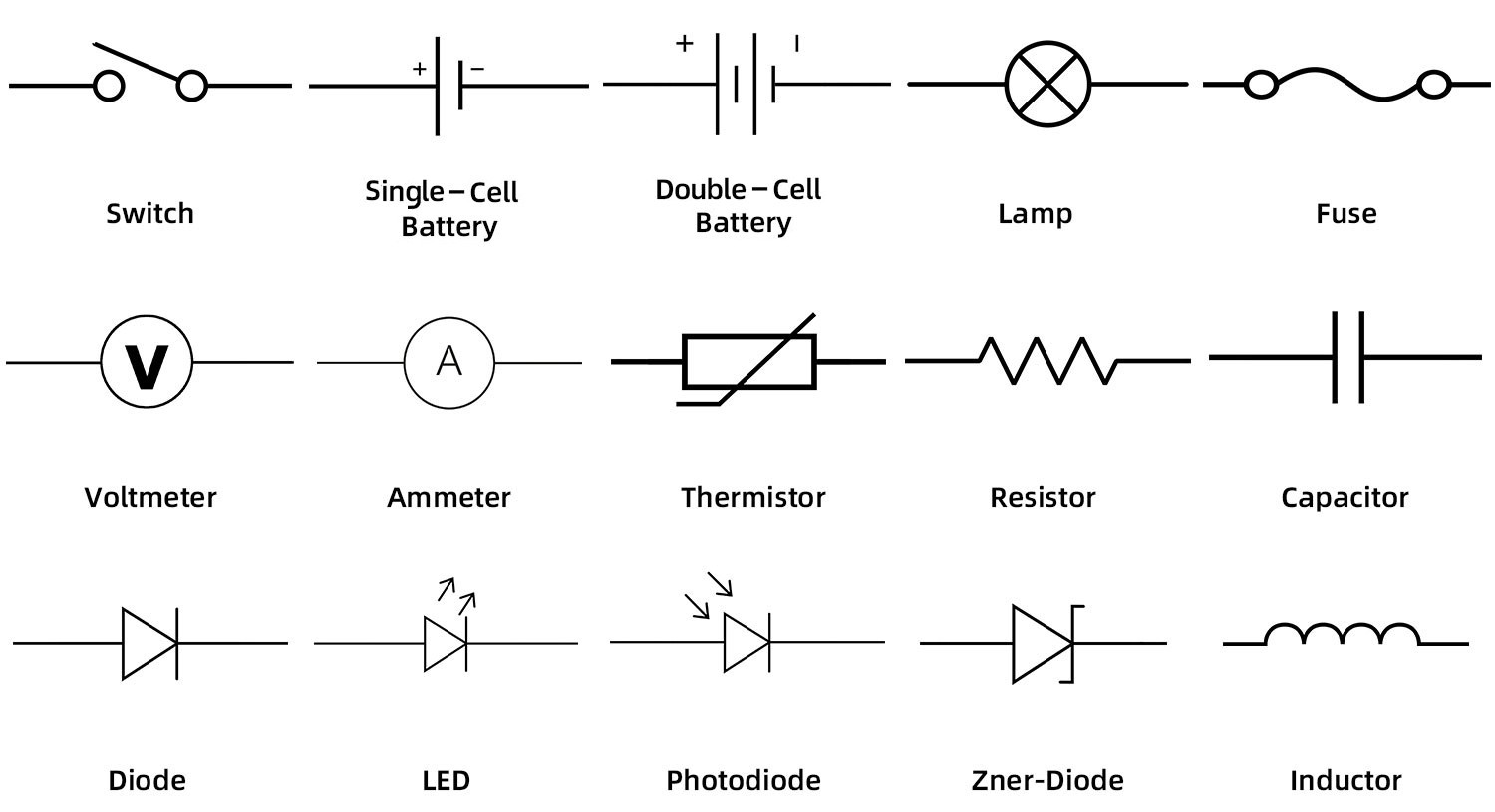
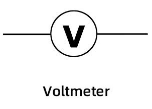
An electric circuit is generally composed of electrical loops which can include wires, batteries (Rule [[[), resistors (Rule [[[), lightbulbs (Rule [[[), capacitors (Rule [[[), switches (Rule [[[), Ammeters (Rule [[[), and Voltmeters (Rule [[[). A final circuit element, inductors (Rule [[[), is dealt with later on in the summaries ([[[) because it requires knowledge of magnetism and inductance, more advanced subjects.
These components are all represented with their own symbols in circuit diagrams. The below illustration displays the most popularly used components in diagrams.
# Open Circuit: A circuit in which there is no closed loop for electrons to flow, thus producing zero net current.
# Closed Circuit: A circuit in which there is a closed loop that enables electrons to flow, producing a current. While a conductor (like copper) connecting two wires will close a circuit, an insulator (like glass) would not.
# Switch: An electrical component that only serves to close or open a circuit. When the switch is shut, it closes the circuit, and when it is open, then the circuit is open as well, resulting in all of the aforementioned effects (see above definitions). Switches are represented using the following symbol:
XVIII.II Batteries.
#
P. Rule .
Battery:
Batteries are the source of the electric potential difference between the positive and negative ends of a circuit. It is, thus, inherently the source of the electromotive force (when idealized), described in Rule [[[.
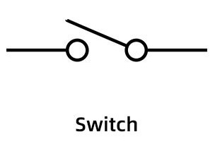
In a circuit diagram, a battery is represented with two plates of differing signs, with the positive and negative sides clearly labeled. When viewing a circuit, it should ALWAYS be followed as having the current start from the positive end (for the reasons originally noted in Rule [[[) and move along the circuit towards the negative end.
 The electric symbols for single-cell and double-cell batteries. Courtesy of NextPCB.
The long line of the battery is the positive terminal, while the short line is the negative terminal. Furthermore, when the battery is ideal and has no internal resistance, the electromotive force symbol (see Rule [[[) is placed near the battery on the circuit, since the battery is the starting and ending point of the electric potential difference. For more details as to internal resistance and how one should deal with it, see Rule [[[.
For information as to battery "cells", see Rule [[[+1. See Rule [[[ for relevant information about internal resistance.
Batteries are the source of the electric potential difference between the positive and negative ends of a circuit. It is, thus, inherently the source of the electromotive force (when idealized), described in Rule [[[.
In a circuit diagram, a battery is represented with two plates of differing signs, with the positive and negative sides clearly labeled. When viewing a circuit, it should ALWAYS be followed as having the current start from the positive end (for the reasons originally noted in Rule [[[) and move along the circuit towards the negative end.
The long line of the battery is the positive terminal, while the short line is the negative terminal. Furthermore, when the battery is ideal and has no internal resistance, the electromotive force symbol (see Rule [[[) is placed near the battery on the circuit, since the battery is the starting and ending point of the electric potential difference. For more details as to internal resistance and how one should deal with it, see Rule [[[.
For information as to battery "cells", see Rule [[[+1. See Rule [[[ for relevant information about internal resistance.
#
P. Rule .
Battery Cells:
The electric potential difference supplied by the battery is determined by the number of "cells" within a battery. Each cell produces a fixed amount of electric potential difference, and by adding more, the total electric potential difference of the battery (and thus the circuit) will increase, allowing it to drive a greater level of current. Illustrated above in Rule [[[-1 are the symbols for single-cell and double-cell batteries.
The electric potential difference supplied by the battery is determined by the number of "cells" within a battery. Each cell produces a fixed amount of electric potential difference, and by adding more, the total electric potential difference of the battery (and thus the circuit) will increase, allowing it to drive a greater level of current. Illustrated above in Rule [[[-1 are the symbols for single-cell and double-cell batteries.
#
P. Rule .
Current and Voltage in a Circuit:
Within a circuit, the electric current will always remain constant when the path is undivided. On an individual level, current is constant across each electrical component (whether resistor or capacitor or whatever). The reason for this is explained in Rule [[[understandingheart[[[.
The only times in which the current running through a circuit can differ at two places is when the circuit path is divided - i.e., when the circuit has a junction (a splitting of the wires onto separate paths), with the electrical components along the paths being "parallel". See Rule [[[ for more information regarding this phenomenon. The circuit will always have its paths reconverge by the time the negative terminal is reached, and so the current through both terminals is always the same.
The Electric Potential Difference (Voltage) will, of course, fluctuate as the charge moves from one end of the circuit to the other, as the "difference" will inherently decrease between the two ends of the battery (for example, a "5V" circuit has an electric potential of 5 Volts on the positive terminal and 0 Volts on the negative terminal).
Voltage will only lower, however, as the charge passes through an electrical component, and not while going through a resistance-less wire (see Rule [[[). Thus, the electric potential difference between the farthest extent of the wire connected to the positive terminal and the wire connected to the negative terminal will be the same as that between the terminals (the Terminal Voltage).
Electric potential decreases with every electrical component, decreasing the electric potential difference between the charge position and the negative terminal with each component passed through.
It's important to note that across the different paths of a parallel set (see Rule [[[), Voltage will be the same. This is true regardless of how unbalanced the component distribution is between the paths - regardless of whether there are five components on one path and two components on the other. Thus, for parallel paths, as the Voltage is the same, if the components on the paths are not identical to eachother, then the current will differ between the two paths to compensate for the different resistance (under the VCR Law, Rule [[[), retaining the same Voltage across the paths.
It is standard convention to treat the negative terminal of a battery as a zero-Volt reference point, with the positive terminal having x number of Volts to start with, and by the time it gets to the end of the circuit loop, reaching zero. Of course, a 9V circuit could have 10 V on the positive and 1 V on the negative (since difference is relative), but where not otherwise stated, assume the circuit has the negative terminal set as a 0 V reference point. In [[[kirchhoff's 2nd law - create a little narrative here giving an exact scientific reason for why Voltage must cancel out and whatever[[[
#
P. Rule .
Upon occasion, a foolish question will ask you to find the Voltage/electric potential difference of a component. In these cases, just mentally rephrase the question to ask for the "Voltage across" the component, which is a more logical phrasing of such a question.
Of course, it is perfectly logical to ask for the current of a component, or the resistance/capacitance of a component, but since Voltage is inherently a difference between two points (the effect of the component on which is being measured), it is more accurate to ask for the Voltage across.
Of course, it is perfectly logical to ask for the current of a component, or the resistance/capacitance of a component, but since Voltage is inherently a difference between two points (the effect of the component on which is being measured), it is more accurate to ask for the Voltage across.
#
P. Rule .
Terminal Voltage: SCALAR.
Units: Volts, e.g. Joules / Coulombs. The symbol for the Volts unit, hilariously, is the same as the symbol for electric potential: V.
Equation:
ΔVt = Ɛ (when in an ideal battery)
∆Vt = Ɛ - (I × r) (when in a non-ideal battery)
ΔVt = Terminal Voltage, the total measured electric potential difference supplied between the terminals of a battery.
Ɛ = Electromotive Force, the maximum possible electric potential difference between the terminals of the battery, only achievable when the battery is ideal without any internal resistance.
I = The current flowing through the non-ideal battery.
r = The internal resistance of a non-ideal battery.
Definition: Terminal Voltage is the total measured electric potential difference supplied between the positive and negative terminals of the battery. Note that this represents the actual, measured value of the potential difference, which, in an ideal battery, would be unimpeded by such things like internal resistance and would reflect the greatest possible electric potential difference between the terminals, known as the electromotive force (see Rule [[[).
The difference between the Terminal Voltage of a non-ideal battery and the ideal electromotive force (see Rule [[[) is the electric potential difference of the internal resistance of the battery, ΔVr. This electric potential difference is then simplified into into its components by the VCR law (Rule [[[), thus creating the non-ideal equation seen above.
For all non-ideal batteries, the Terminal Voltage across the battery will decrease as the current through the battery increases, forming an inverse relationship. As one can figure out after momentary analysis, when there is no current in a non-ideal battery, the Terminal Voltage would equal to that of the electromotive force (as internal resistance would equal to zero).
#
P. Rule .
Electromotive Force (emf):
The maximum possible electric potential difference a battery can provide between its negative and positive terminals is known as the electromotive force, known as "emf" to the commonfolk. Represented using Ɛ.
In all non-ideal batteries, the emf will be greater than the actual electrical potential difference of the circuit (the Terminal Voltage, see definition), since internal resistance will screw with it and ruin the perfection. In all ideal batteries however, terminal velocity is equivalent to electric potential difference.
Importantly, note that electromotive force is not a force. The cabal PURPOSELY named it like that so that you would get confused and include it on your free-body diagram. THIS IS EXACTLY WHAT THEY WANT YOU TO DO. It is only a reference to the max electric potential difference, not a force.
#
P. Rule .
Internal Resistance:
Idealized batteries, the most commonly used in Physics, are totally without internal resistance. Batteries with internal resistance are known as "Nonideal batteries", while any circuit that has internal resistance of any kind (whether in a battery or within a wire) is known as a "Nonideal circuit".
When a battery is said to have some sort of "internal resistance", just imagine that there is a resistor immediately following the positive terminal of the battery (with no inbetween wire). If a WIRE is said to have internal resistance, just do the same - fashion a resistor at the very beginner of the wire, and it will have the same effect.
Lowercase r is typically the symbol of internal resistance of a battery. When the internal resistance is nonzero, the electrical current will increase as the Terminal Voltage decreases (as ∆Vt = Ɛ - Iinternal, see Rule [[[-1). Thus, with a nonzero internal resistance the only way to get emf equal to Terminal Voltage is for there to be zero current.
Most problems will deal with ideal batteries, and will otherwise inform you of such unideal attributes like internal resistance.
#
P. Rule .
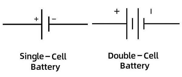
Voltmeter:
The Voltmeter component is used to measure electric potential difference. It can be strategically placed in the circuit to obtain a value that reflects the Voltage across another component, as a result of Voltage being the same for all components in parallel (see Rule [[[Current and Voltage in a Circuit[[[).
The Voltmeter must be placed in parallel with the electrical component it is measuring the 'Voltage-across' of.
The resistance of a Voltmeter is near infinite (infinite for all intents and purposes), as it must prevent ANY current from moving onto its path (under the current divider law of Rule [[[), as otherwise it will actually provide a parallel path to the component being measured and will decrease the equivalent resistance of the circuit, increasing the current and ruining everything (and interfering with the purely observatory nature of the Voltmeter).
Voltmeters are represented using the following symbol:
 The electric symbol for a Voltmeter. Courtesy of NextPCB.
The Voltmeter component is used to measure electric potential difference. It can be strategically placed in the circuit to obtain a value that reflects the Voltage across another component, as a result of Voltage being the same for all components in parallel (see Rule [[[Current and Voltage in a Circuit[[[).
The Voltmeter must be placed in parallel with the electrical component it is measuring the 'Voltage-across' of.
The resistance of a Voltmeter is near infinite (infinite for all intents and purposes), as it must prevent ANY current from moving onto its path (under the current divider law of Rule [[[), as otherwise it will actually provide a parallel path to the component being measured and will decrease the equivalent resistance of the circuit, increasing the current and ruining everything (and interfering with the purely observatory nature of the Voltmeter).
Voltmeters are represented using the following symbol:
#
P. Rule .
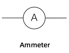
Ammeter:
The Ammeter component is used to measure current, or the number of amperes moving through the circuit at a point. It can be strategically placed in the circuit to obtain a value that reflects the current of another component, as a result of current being the same for all components in series (see Rule [[[Current and Voltage in a Circuit[[[).
The Ammeter must be placed in series with the electrical component it is measuring the 'current-passing-through' of.
The resistance of an Ammeter is near zero (relatively zero for all intents and purposes), as otherwise the equivalent resistance of the circuit will increase and thus the current will decrease, interfering with the purely observatory nature of the Ammeter.
Ammeters are represented using the following symbol:
 The electric symbol for an Ammeter. Courtesy of NextPCB.
The Ammeter component is used to measure current, or the number of amperes moving through the circuit at a point. It can be strategically placed in the circuit to obtain a value that reflects the current of another component, as a result of current being the same for all components in series (see Rule [[[Current and Voltage in a Circuit[[[).
The Ammeter must be placed in series with the electrical component it is measuring the 'current-passing-through' of.
The resistance of an Ammeter is near zero (relatively zero for all intents and purposes), as otherwise the equivalent resistance of the circuit will increase and thus the current will decrease, interfering with the purely observatory nature of the Ammeter.
Ammeters are represented using the following symbol:
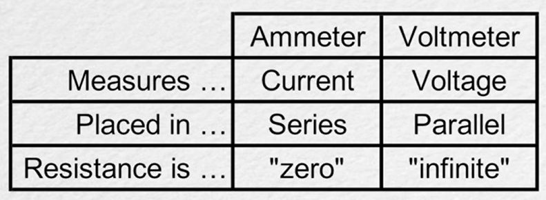
# Ammeter/Voltmeter Memorization Table:
XVIII.III Resistors.
#
P. Rule .
The Understanding At The Heart Of Resistors:
Resistors are the electrical components that have the property of resistance, causing the electric current of the circuit to decrease.
The cabal has cleverly defined resistance as "the ability to resist the flow of electric current". This loses all meaning when one discovers that electrical current is the exact same before and after passing through a resistor. It begs the question: What exactly does a resistor do?
The best way to imagine the effect of the resistor is to realize that it, through the VCR Law, will have a universal effect. When a charge goes through a resistor, it will indeed get slower, and thus will have a lower electrical current. HOWEVER: because all the charges in the circuit are jammed packed together in a line, all of the charges behind those in the resistor will slow down, as they cannot move any faster. As a result, every charge in the circuit will move at the exact same speed when following an individed path (i.e., in series).
In other words, the constant electric current of a circuit is dependent on the total resistance (the equivalent resistance) of the circuit. The greater the strength of a single resistor on one end of the circuit, the lesser the strength of the current throughout the entire. circuit.
All components in series will have the same current, while it will differ between components in parallel (explained below).
It helps to not imagine the charges as individuals detached from the whole, but rather as a sludge, moving together at a constant rate (the current). This sludge, when divided into multiple paths (such as through a junction, which creates parallel components along its individual paths - see Rule [[[), can indeed become slower in its split form along its individual paths (the division of speed of which unto the different paths in fact not being equal, but rather calculated in a specific manner (Rule [[[)), but if the path remains undivided, the sludge will always move at a constant rate.
#
P. Rule .
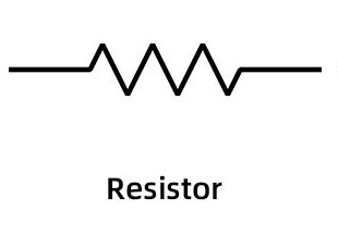
Resistors:
The electrical component that acts as an instrument of resistance to the current. It is THE resistor, nobly standing against a raging electric potential energy.
When a charge passes through a resistor, the electric potential difference will change (as potential energy gets dissipated) while the current will remain constant. Current will remain the same before and after passing through the resistor, conserving charge.
Consider the VCR Law (Rule [[[) on a localized scale, only considering a single resistor. In this scenario, the VCR Law would produce the specs for the state of the charge in the wire immediately following the resistor - this is the data that must be used to discern the effect of any electrical component immediately following the resistor.
Below is the standard depiction of a resistor in circuit diagrams. Occasionally, resistors will be represented as a lame rectangular box instead of a zigzag, the box being small enough that it would not be confused for a junction of wires.
 The symbol for the resistor electrical component. Courtesy of NextPCB.
The electrical component that acts as an instrument of resistance to the current. It is THE resistor, nobly standing against a raging electric potential energy.
When a charge passes through a resistor, the electric potential difference will change (as potential energy gets dissipated) while the current will remain constant. Current will remain the same before and after passing through the resistor, conserving charge.
Consider the VCR Law (Rule [[[) on a localized scale, only considering a single resistor. In this scenario, the VCR Law would produce the specs for the state of the charge in the wire immediately following the resistor - this is the data that must be used to discern the effect of any electrical component immediately following the resistor.
Below is the standard depiction of a resistor in circuit diagrams. Occasionally, resistors will be represented as a lame rectangular box instead of a zigzag, the box being small enough that it would not be confused for a junction of wires.
#
P. Rule .
Unless otherwise stated, all wires are considered ideal and have zero resistance.
Under ideal conditions, wires are considered to have zero resistance, and so electrical potential difference will remain the same from one end of the wire to the other, so long as there are no intervening electric components in between. The second there is an electrical component, then there will be a change in electrical potential.
There must always be an electric potential difference between the beginning and end of the circuit, obviously. The ending Electric Potential must be different from the beginning. Otherwise, there would be no current.
#
P. Rule .
Lightbulbs:
Where there is a symbol for a lightbulb (oftentimes denoted as a "lamp"), treat it as a resistor (Rule [[[).
The brightness of a lightbulb increases with high electric power, and decreases with low electric power, which is obvious considering that brightness is just the dissipation of heat, a euphemism for electric power (see Rule [[[).
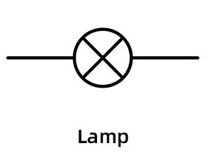 The electrical component symbol for a Lamp, also known as a lightbulb. Courtesy of NextPCB.
Where there is a symbol for a lightbulb (oftentimes denoted as a "lamp"), treat it as a resistor (Rule [[[).
The brightness of a lightbulb increases with high electric power, and decreases with low electric power, which is obvious considering that brightness is just the dissipation of heat, a euphemism for electric power (see Rule [[[).
#
P. Rule .
Electrical Load:
The part of the circuit which converts electric potential energy into heat, sound, or light, effectively dissipating it into nonconservative energy lost to the system. This part can be the resistor or anything else that has resistance.
The battery can never be a part of electrical load, because it is an electrical power source (the origin of all electric potential difference).
#
P. Rule .
Short Circuit:
A circuit which has a very small resistance and thus a very large current is known as a "short circuit". This makes some unstable, since with little resistance and constant Voltage the electric power can be very large and dangerous, as discernable by the equation presented in Rule 232.
A circuit cannot be a circuit if it does not have any resistance. Judging by the VCR Law, a circuit with zero resistance would have infinite current, which is preposterous. All circuits must have some form of resistance, internal/resistor or otherwise.
XVIII.IV Capacitors.
Capacitors store electric potential energy within their electric field, something that gives them unique properties in circuitry. The actual purpose for capacitors in doing so within a circuit, as is taught and is fundamental to Electric Engineering (see E.E. Rule [[[), has to do with Voltage regulation, as current from a battery will come in little bursts rather than in a coherent flow.
However, in freshman Physics, which deals only with the most idealized circuits imaginable, and almost entirely with DC circuits (constant current, see Rule 223), this purpose is all but neglected.
Instead, the more potent and relevant attributes of capacitors, particularly how they play into series and parallel circuits, will be described here somewhat detached from their actual purpose - indeed, this section reflects how to solve problems involving capacitors and their application in Physics rather than anything geared toward actual engineering.
Unless told otherwise (and as previously stated in Rule [[[), every circuit and application of current & Voltage should be assumed to be in DC current (see Rule [[[), with current constant as it moves from the battery.
XVIII.V Series & Parallel.
#
P. Rule .
Circuits can be generalized into two specific patterns/relations that can occur between its constituent components:
Rather amusingly, as seen in Rule [[[resistor[[[ and Rule [[[capacitor[[[, the equations for equivalent resistance and equivalent capacitance are reversed with respect to series and parallel.
Below, there can be seen an example of resistors in series and parallel. Note that the same patterns hold for capacitors and all other components that may get into series and parallel:
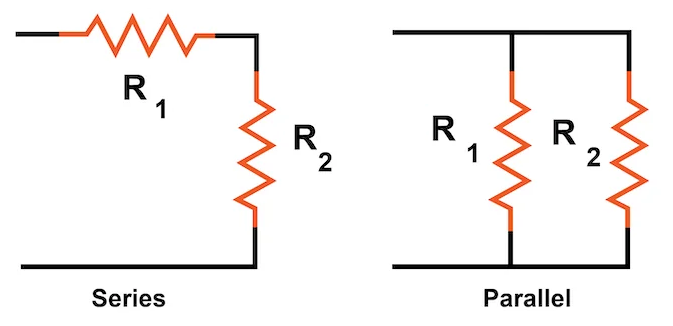 Resistors in Series and Parallel. Courtesy of AllAboutCircuits.
- Series: A situation between two electrical components in which the charge going through the first component must go through the second component. E.g., the components form a direct path with one another.
- Parallel: A situation between two electrical components in which the charge, as a result of a junction, will either go through one component or the other. The paths of the two components will then reconverge without going through another element.
Rather amusingly, as seen in Rule [[[resistor[[[ and Rule [[[capacitor[[[, the equations for equivalent resistance and equivalent capacitance are reversed with respect to series and parallel.
Below, there can be seen an example of resistors in series and parallel. Note that the same patterns hold for capacitors and all other components that may get into series and parallel:
# Set: The particular parameterized region in which the components in series or parallel are located. The 'set' of the left circuit in the image shown at the bottom of Rule [[[-1 extends from the wire directly before R1 to the wire directly after R2.
The total Voltage of a 'set' in series only reflects the electric potential difference between those beginning and ending points - not the electric potential difference of the circuit as a whole (though, if the beginning and ending wires connect to the terminals, the Voltage of set will indeed be the Voltage of the circuit).
# Equivalent Resistance: Typically denoted using Req, Equivalent Resistance is the total summed values of all resistances within a circuit (measured in Ohms), summed with respect to their nature as resistors in series or parallel (see Rule [[[full analysis[[[). It is calculated using a substitution of the VCR Law.
The "Equivalent Resistance" of two or a specific set of resistors is just the summed total of those specific resistors, excluding all others in the circuit.
# Equivalent Capacitance: Typically denoted using Ceq, Equivalent Capacitance is the total summed values of all capacitances within a circuit (measured in Farads), summed with respect to their nature as capacitors in series or parallel (see Rule [[[full analysis[[[). It is calculated using a substitution of the capacitance equation (Rule 213).
The "Equivalent Capacitance" of two or a specific set of capacitors is just the summed total of those specific capacitors, excluding all others in the circuit.
# Junction: A point in which the wire of a circuit splits into two or more paths.
All parallel sections of a circuit have a diverging junction and a reconverging junction, specifically only involving a splitting into two paths/wires max - see Rule [[[big original one[[[.
#
P. Rule .
Resistors in Series & Parallel (Full Analysis):
Resistors in Series and Parallel. Courtesy of AllAboutCircuits.
The left circuit above depicts two resistors in series, while the right circuit depicts two resistors in parallel.
Finding Equivalent Resistance for series and parallel sets requires finding other relationships, involving the likes of electric potential energy and current, in order to cancel out values using the VCR Law. See the "Series" and "Parallel" sections below for how this is done, and see Rule [[[ for a truncated version that only includes the equations for quick reference.
IT = I1 = I2, where I1 & I2 are the currents running through the two resistors, and IT is the general current running through the terminals of the battery.
When the two resistors are in series, the electric potential difference between the wire directly before the first resistor and the wire directly after the second resistor (which would be the wires connected to the terminals if there are no other components in the circuit) is equivalent to to the summed electric potential difference across the two resistors.
In short, as depicted below, Ɛ = ΔV1 + ΔV2, with Ɛ being ΔVset when there are more components in the circuit than just the two resistors.
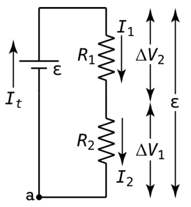 A simple circuit in which two resistors are in series. Courtesy of Flipping Physics.
By substituting in values from the VCR Law into the aforementioned equation, and then canceling out current (since the current is equal everywhere in series), the following equation can be established for equivalent resistance of a particular resistor set (for an 'n' number of resistors in series):
$$R_{\text{set series}} = \sum_n R_n = R_1 + R_2 + \dots$$
Thus, when a resistor is added into a series, the equivalent resistance increases.
ΔVset = ΔV1 = ΔV2
As for the current that moves through the split paths of a junction, it cannot be assumed that the current will split evenly between the two paths. In fact, all that is known about the individual path currents is the conservation of charge, delineated in the following equation:
It = I1 + I2
It, of course, is referring to the current before the diverging junction and after the converging junction. It is only ever represents the current running through the terminals if there are no other components in the circuit than the resistors in parallel.
In the same manner as was done before for series (now simply using different variables), the values of the VCR equation can be substituted into the above equation, and then have Voltage canceled out everywhere (since it was previously shown to be the same across every component). Thus, the following equation can be established, describing the equivalent resistance of 'n' resistors in parallel:
$$R_{\text{set parallel}} = \left( \sum_n \frac{1}{R_n} \right)^{-1} = \left( \frac{1}{R_1} + \frac{1}{R_2} + \dots \right)^{-1}$$
I.E., for resistors in parallel, the equivalent resistance is equal to the inverse of the sum of the inverses of all resistors in the set. Remember that in order to be parallel, there must only be one component on each split path before they reconverge.
Thus, when a resistor is added in parallel, the equivalent resistance decreases.
The left circuit above depicts two resistors in series, while the right circuit depicts two resistors in parallel.
Finding Equivalent Resistance for series and parallel sets requires finding other relationships, involving the likes of electric potential energy and current, in order to cancel out values using the VCR Law. See the "Series" and "Parallel" sections below for how this is done, and see Rule [[[ for a truncated version that only includes the equations for quick reference.
Resistors in Series:
When two resistors are in series, the current running through them is the same:IT = I1 = I2, where I1 & I2 are the currents running through the two resistors, and IT is the general current running through the terminals of the battery.
When the two resistors are in series, the electric potential difference between the wire directly before the first resistor and the wire directly after the second resistor (which would be the wires connected to the terminals if there are no other components in the circuit) is equivalent to to the summed electric potential difference across the two resistors.
In short, as depicted below, Ɛ = ΔV1 + ΔV2, with Ɛ being ΔVset when there are more components in the circuit than just the two resistors.
By substituting in values from the VCR Law into the aforementioned equation, and then canceling out current (since the current is equal everywhere in series), the following equation can be established for equivalent resistance of a particular resistor set (for an 'n' number of resistors in series):
$$R_{\text{set series}} = \sum_n R_n = R_1 + R_2 + \dots$$
Thus, when a resistor is added into a series, the equivalent resistance increases.
Resistors in Parallel:
When resistors are in parallel, the electric potential difference across each resistor is equal to that of the electric potential difference between the wire before the diverging junction and the wire after the reconverging junction:ΔVset = ΔV1 = ΔV2
As for the current that moves through the split paths of a junction, it cannot be assumed that the current will split evenly between the two paths. In fact, all that is known about the individual path currents is the conservation of charge, delineated in the following equation:
It = I1 + I2
It, of course, is referring to the current before the diverging junction and after the converging junction. It is only ever represents the current running through the terminals if there are no other components in the circuit than the resistors in parallel.
In the same manner as was done before for series (now simply using different variables), the values of the VCR equation can be substituted into the above equation, and then have Voltage canceled out everywhere (since it was previously shown to be the same across every component). Thus, the following equation can be established, describing the equivalent resistance of 'n' resistors in parallel:
$$R_{\text{set parallel}} = \left( \sum_n \frac{1}{R_n} \right)^{-1} = \left( \frac{1}{R_1} + \frac{1}{R_2} + \dots \right)^{-1}$$
I.E., for resistors in parallel, the equivalent resistance is equal to the inverse of the sum of the inverses of all resistors in the set. Remember that in order to be parallel, there must only be one component on each split path before they reconverge.
Thus, when a resistor is added in parallel, the equivalent resistance decreases.
#
P. Rule .
Resistors in Series & Parallel (Truncated):
ΔVset = ΔV1 + ΔV2
$$R_{\text{set series}} = \sum_n R_n = R_1 + R_2 + \dots$$
ΔVset = ΔV1 = ΔV2 $$R_{\text{set parallel}} = \left( \sum_n \frac{1}{R_n} \right)^{-1} = \left( \frac{1}{R_1} + \frac{1}{R_2} + \dots \right)^{-1}$$
Series:
IT = I1 = I2ΔVset = ΔV1 + ΔV2
$$R_{\text{set series}} = \sum_n R_n = R_1 + R_2 + \dots$$
Parallel:
It = I1 + I2ΔVset = ΔV1 = ΔV2 $$R_{\text{set parallel}} = \left( \sum_n \frac{1}{R_n} \right)^{-1} = \left( \frac{1}{R_1} + \frac{1}{R_2} + \dots \right)^{-1}$$
#
P. Rule .
Capacitors in Series & Parallel (Full Analysis):
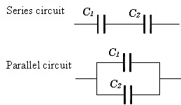 Capacitors in Series and Parallel. Courtesy of Electric Shocks.
The top circuit above depicts two capacitors in series, while the bottom circuit depicts two capacitors in parallel.
Finding Equivalent Capacitance for series and parallel sets requires finding other relationships, involving the likes of electric potential energy and charge, in order to cancel out values using the capacitance equation of Rule 213. See the "Series" and "Parallel" sections below for how this is done, and see Rule [[[ for a truncated version that only includes the equations for quick reference.
When the two capacitors are in series, the electric potential difference between the wire directly before the first capacitor and the wire directly after the second capacitor (which would be the wires connected to the terminals if there are no other components in the circuit) is equivalent to to the summed electric potential difference across the two capacitors. In short, as depicted below, Ɛ = ΔV1 + ΔV2, with Ɛ being ΔVset when there are more components in the circuit than just the two capacitors.
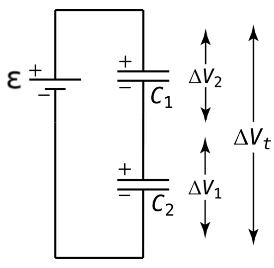 A simple circuit in which two capacitors are in series. Courtesy of Flipping Physics.
As such, since the charges moved by the battery will have to pass through the plates of both capacitors equally, the magnitude of the charge is same for each capacitor:
Qset = Q1 = Q2
Finally, by substituting in values from the standard capacitance equation (Rule 213) into the aforementioned equation, and then canceling out charge (since charge is equal everywhere in series), the following equation can be established for equivalent capacitance of a particular capacitor set (for an 'n' number of capacitors in series):
$$C_{\text{set series}} = \left( \sum_{n} \frac{1}{C_n} \right)^{-1} = \left( \frac{1}{C_1} + \frac{1}{C_2} + \dots \right)^{-1}$$
I.E., for capacitors in series, the equivalent capacitance is equal to the inverse of the sum of the inverses of all capacitors in the set.
Thus, when a capacitor is added in series, the equivalent capacitance decreases.
ΔVset = ΔV1 = ΔV2
As for the current that moves through the split paths of a junction, it cannot be assumed that the current will split evenly between the two paths. In fact, all that is known about the individual path currents is the conservation of charge, delineated in the following equation:
It = I1 + I2
It, of course, is referring to the current before the diverging junction and after the converging junction. It is only ever represents the current running through the terminals if there are no other components in the circuit than the capacitors in parallel.
Furthermore, because the charges moved by the battery to the junction are going to be split between the two paths (between the two capacitors), the charge moved by the battery to the diverging junction (and by conservation of charge, the charge at the converging junction) is equal to the sum of charges across each individual capacitor:
Qset = Q1 + Q2 + ...
The values of the capacitance equation can then be substituted in for charge, leaving only Voltage and Capacitance. Since electric potential energy has already been determined to be the same for all values, it can be canceled out, leaving only the following equation for the equivalent capacitance of a set of 'n' capacitors in parallel:
$$C_{\text{set parallel}} = \sum_{n} C_n = C_1 + C_2 + \dots$$
Thus, when a capacitor is added in parallel, the equivalent capacitance increases.
The top circuit above depicts two capacitors in series, while the bottom circuit depicts two capacitors in parallel.
Finding Equivalent Capacitance for series and parallel sets requires finding other relationships, involving the likes of electric potential energy and charge, in order to cancel out values using the capacitance equation of Rule 213. See the "Series" and "Parallel" sections below for how this is done, and see Rule [[[ for a truncated version that only includes the equations for quick reference.
Capacitors in Series:
When two capacitors are in series, the current running through them is the same: IT = I1 = I2, where I1 & I2 are the currents running through the two capacitors, and IT is the general current running through the terminals of the battery.When the two capacitors are in series, the electric potential difference between the wire directly before the first capacitor and the wire directly after the second capacitor (which would be the wires connected to the terminals if there are no other components in the circuit) is equivalent to to the summed electric potential difference across the two capacitors. In short, as depicted below, Ɛ = ΔV1 + ΔV2, with Ɛ being ΔVset when there are more components in the circuit than just the two capacitors.
As such, since the charges moved by the battery will have to pass through the plates of both capacitors equally, the magnitude of the charge is same for each capacitor:
Qset = Q1 = Q2
Finally, by substituting in values from the standard capacitance equation (Rule 213) into the aforementioned equation, and then canceling out charge (since charge is equal everywhere in series), the following equation can be established for equivalent capacitance of a particular capacitor set (for an 'n' number of capacitors in series):
$$C_{\text{set series}} = \left( \sum_{n} \frac{1}{C_n} \right)^{-1} = \left( \frac{1}{C_1} + \frac{1}{C_2} + \dots \right)^{-1}$$
I.E., for capacitors in series, the equivalent capacitance is equal to the inverse of the sum of the inverses of all capacitors in the set.
Thus, when a capacitor is added in series, the equivalent capacitance decreases.
Capacitors in Parallel:
When capacitors are in parallel, the electric potential difference across each capacitor is equal to that of the electric potential difference between the wire before the diverging junction and the wire after the reconverging junction:ΔVset = ΔV1 = ΔV2
As for the current that moves through the split paths of a junction, it cannot be assumed that the current will split evenly between the two paths. In fact, all that is known about the individual path currents is the conservation of charge, delineated in the following equation:
It = I1 + I2
It, of course, is referring to the current before the diverging junction and after the converging junction. It is only ever represents the current running through the terminals if there are no other components in the circuit than the capacitors in parallel.
Furthermore, because the charges moved by the battery to the junction are going to be split between the two paths (between the two capacitors), the charge moved by the battery to the diverging junction (and by conservation of charge, the charge at the converging junction) is equal to the sum of charges across each individual capacitor:
Qset = Q1 + Q2 + ...
The values of the capacitance equation can then be substituted in for charge, leaving only Voltage and Capacitance. Since electric potential energy has already been determined to be the same for all values, it can be canceled out, leaving only the following equation for the equivalent capacitance of a set of 'n' capacitors in parallel:
$$C_{\text{set parallel}} = \sum_{n} C_n = C_1 + C_2 + \dots$$
Thus, when a capacitor is added in parallel, the equivalent capacitance increases.
#
P. Rule .
Capacitors in Series & Parallel (Truncated):
ΔVset = ΔV1 + ΔV2
Qset = Q1 = Q2 $$C_{\text{set series}} = \left( \sum_{n} \frac{1}{C_n} \right)^{-1} = \left( \frac{1}{C_1} + \frac{1}{C_2} + \dots \right)^{-1}$$
ΔVset = ΔV1 = ΔV2
Qset = Q1 + Q2 + ... $$C_{\text{set parallel}} = \sum_{n} C_n = C_1 + C_2 + \dots$$
Series:
IT = I1 = I2ΔVset = ΔV1 + ΔV2
Qset = Q1 = Q2 $$C_{\text{set series}} = \left( \sum_{n} \frac{1}{C_n} \right)^{-1} = \left( \frac{1}{C_1} + \frac{1}{C_2} + \dots \right)^{-1}$$
Parallel:
IT = I1 + I2ΔVset = ΔV1 = ΔV2
Qset = Q1 + Q2 + ... $$C_{\text{set parallel}} = \sum_{n} C_n = C_1 + C_2 + \dots$$
XVIII.VI Circuitry Conservation Principles.
Kirchhoff's Laws, hereafter referred to as the Circuitry Conservation Principles (CCP), are a set of two rules that describe basic characteristics about circuitry that can be applied in practically all circumstances (all circumstances that will be faced by the junior physicist).
There are two fundamental rules of the CCP that must always be kept in mind when doing circuitry problems: the Loop Rule and the Junction Rule, described in Rule [[[+1 and Rule [[[+2, respectively.